Semiconductor acceleration sensor and its self-diagnosing method

Inactive Publication Date: 2001-05-15
AKEBONO BRAKE IND CO LTD +1
View PDF10 Cites 74 Cited by
  • Summary
  • Abstract
  • Description
  • Claims
  • Application Information

AI Technical Summary

Problems solved by technology

Those conventional sensors are bulky, and are made up of a number of components, and therefore it is n

Method used


Image

  • Semiconductor acceleration sensor and its self-diagnosing method
  • Semiconductor acceleration sensor and its self-diagnosing method
  • Semiconductor acceleration sensor and its self-diagnosing method

Examples


first embodiment

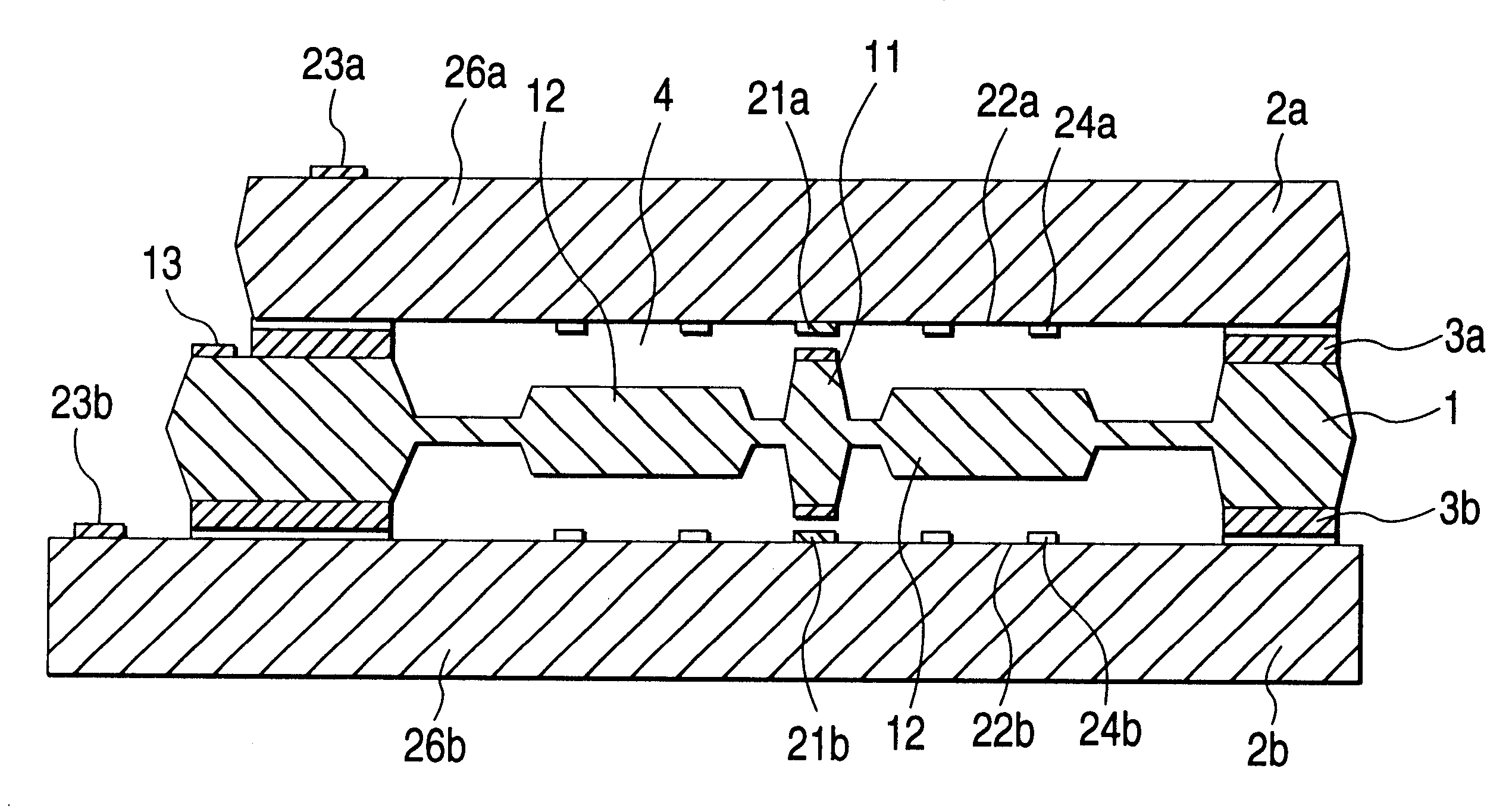
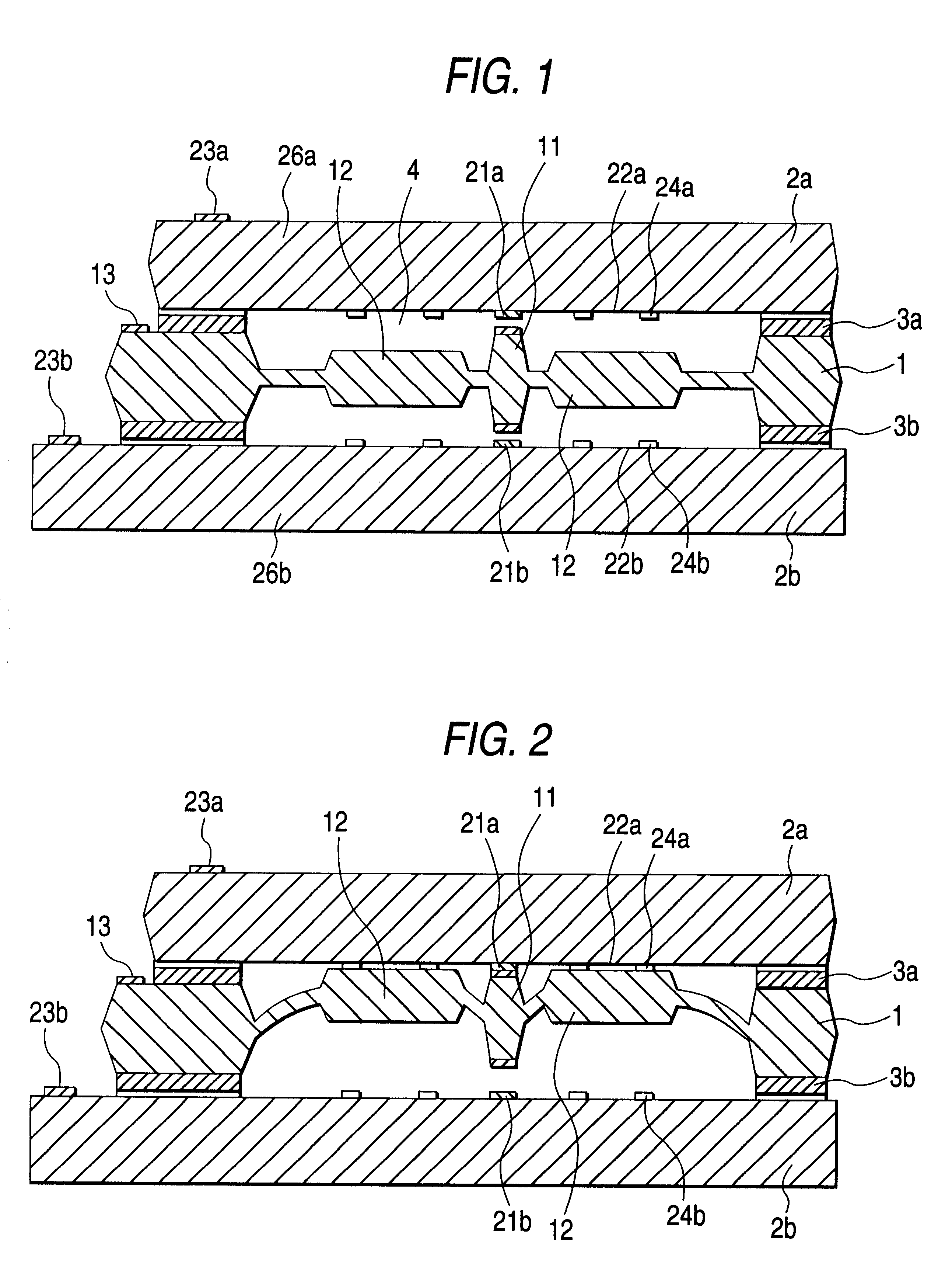
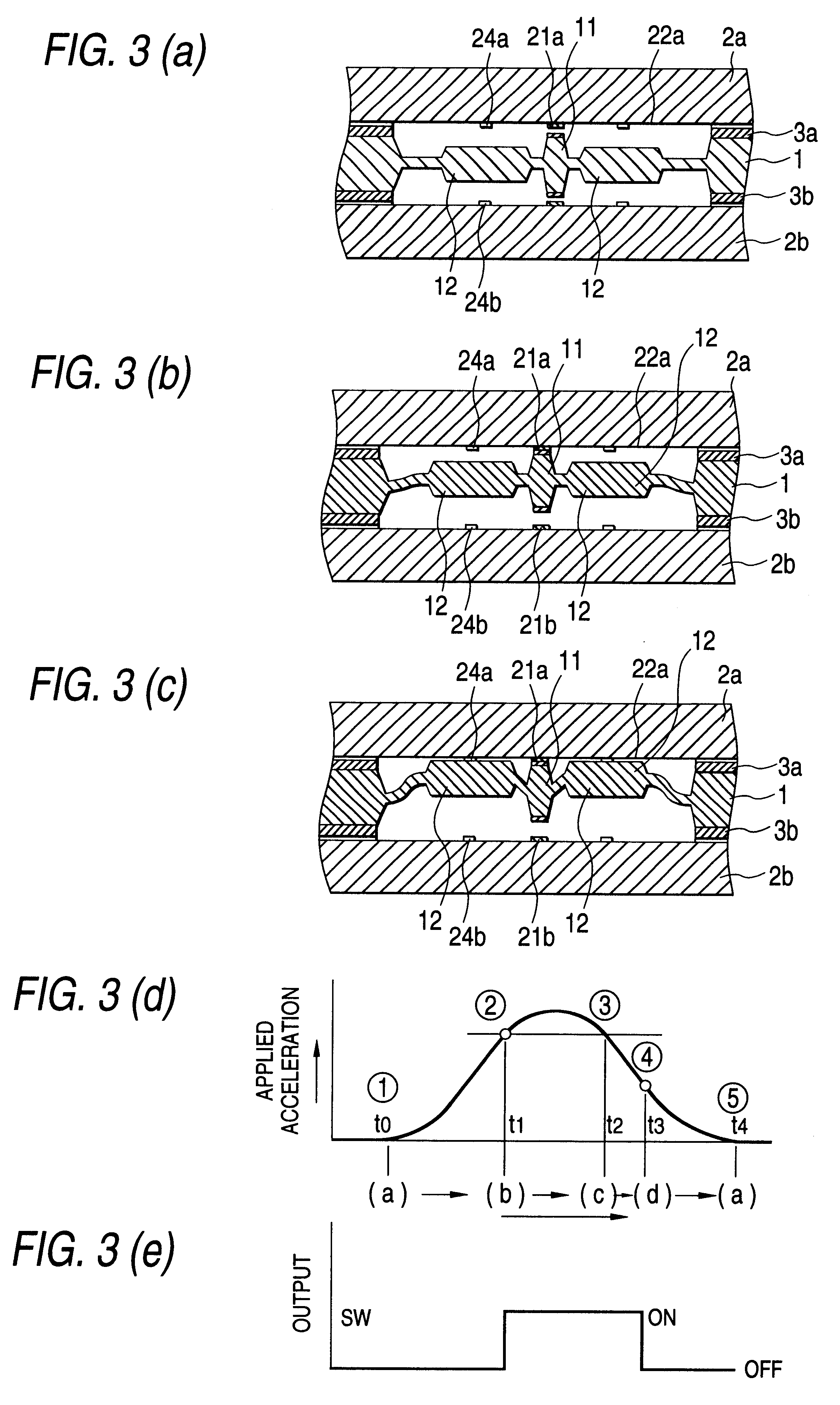
The first embodiment will be described with reference to FIGS. 1 through 8. The semiconductor acceleration sensor, the first embodiment, is to detect whether or not an acceleration in the direction of lamination of a layered product is larger than a predetermined value, and, as shown in FIG. 2, comprises a central board 1, outside boards 2a and 2b, and sealing insulation sections 3a and 3b, which form the layered product. The central board 1 is, for instance, made of Si, and includes a central contact section 11, a weight 12, and a central terminal section 13. The outside boards 2a and 2b are, for instance, made of Si, and includes outside contact sections 21a and 21b, weight confronting sections 22a and 22b, and outside terminal sections 23a and 23b. Since the central board 1 and the outside board 2 is made of a conductive material, Si, and therefore the central contact section 11 and the outside contact section 21 are connected to the central terminal section 13 and the outside te...


PUM


Abstract

The invention provides a semiconductor acceleration sensor which is small in size, light in weight, simple in manufacture, low in manufacturing cost, and high in accuracy, and which, with a switch-on time set to a predetermined value, is stable in operation.In a semiconductor acceleration sensor in which a central board 1 having a central contact section 11, and outside boards 2 at least one of which has an outside contact section 21 are stacked; the central board 1 has a weight 12 near the central contact section 11, and the outside board 2 having the outside contact section 21 has a weight confronting section 11 which confronts with the weight 12, for squeezed damping effect.

Description

The present invention relates to a semiconductor speed sensor, and its self-diagnosing method, and more particularly to a semiconductor acceleration sensor, and its self-diagnosing method which utilizes a squeezed film effect.1. Background ArtAn example of a conventional acceleration sensor employs a ball (like an iron ball). In the sensor, when an acceleration greater than a predetermined value is applied to the sensor, the ball is moved to operate a switch. In another example of the conventional acceleration sensor, a mercury switch is employed (cf. Japanese Utility Patent Application (OPI) No. 4-136575 / 1992 and 127574 (the term "OPI" as used herein means an "unexamined published application"). Those conventional sensors are bulky, and are made up of a number of components, and therefore it is necessary to determined a particular position to install them, and they are high in manufacturing cost.An object of the invention is to provide a semiconductor acceleration sensor which is s...

Claims


Application Information

Patent Timeline
IPC IPC(8): G01P15/08G01P15/135H01H35/14H01H1/00G01P21/00G01P15/02H01L29/84
CPCG01P15/0802G01P15/135H01H35/142H01H1/0015H01H1/0036
Inventor MATSUNAGA, TADAOKUNIMI, TAKASHINEZU, MASAHIROMORI, MASATOMOESASHI, MASAYOSHI
Owner AKEBONO BRAKE IND CO LTD
Why Eureka
Try Eureka