Pressing tool

a technology of pressing tools and clamping tools, applied in the direction of shaping tools, basic electric elements, electrical appliances, etc., can solve the problems of uncontrollable ejection of clamping tools, increased accident risk of pressing tools, and already occurring work accidents

Inactive Publication Date: 2001-06-12
VON ARX AG
View PDF10 Cites 56 Cited by
  • Summary
  • Abstract
  • Description
  • Claims
  • Application Information

AI Technical Summary

Problems solved by technology

However, such pressing tools are tools with an increased accident risk.
Several work accidents have already occurred, wherein the clamping tool was ejected in an uncontrolled manner and the fork-shaped receiver was bent open and deformed.
Moreover, these pressing tools preform an increased number of incorrect pressings.
Damages occur with both electro-mechanically and electro-hydraulically operated pressing tools.
Even if the clamping tool is correctly held in the pressing tool, this alone does not assure precise pressing of the pipe-shaped workpieces.
Besides functional reasons of the pressing tool, there are reasons which are connected with unsatisfactory processing.
For example, the tool, or respectively the clamping jaws, can be dirty, so that sufficient closing of the clamping tool cannot be achieved, or the size of the pipe connector or pressing sleeve does not correspond to the size for which the corresponding tool is provided.
Since these pressing tools are often employed at building sites, soiling, in particular of the clamping tool, can hardly be avoided.
Such soiling then often leads to interruptions in the electronic transmission, and therefore to erroneous information.
One problem with transmitting information from the clamping tool to the pressing tool remains.
Appropriate electronics must be integrated into the clamping jaws in addition to elements which are also mechanically intricate.
Here, the functional ability of the checking means is often hard to determine, and the user can also not see whether their functioning is still assured.
Accordingly, the device continuously provides the information that the pressing process is unsatisfactory, while in actuality the pressing process is satisfactory, but there is an error in monitoring.

Method used


Image

  • Pressing tool
  • Pressing tool
  • Pressing tool

Examples


Embodiment Construction

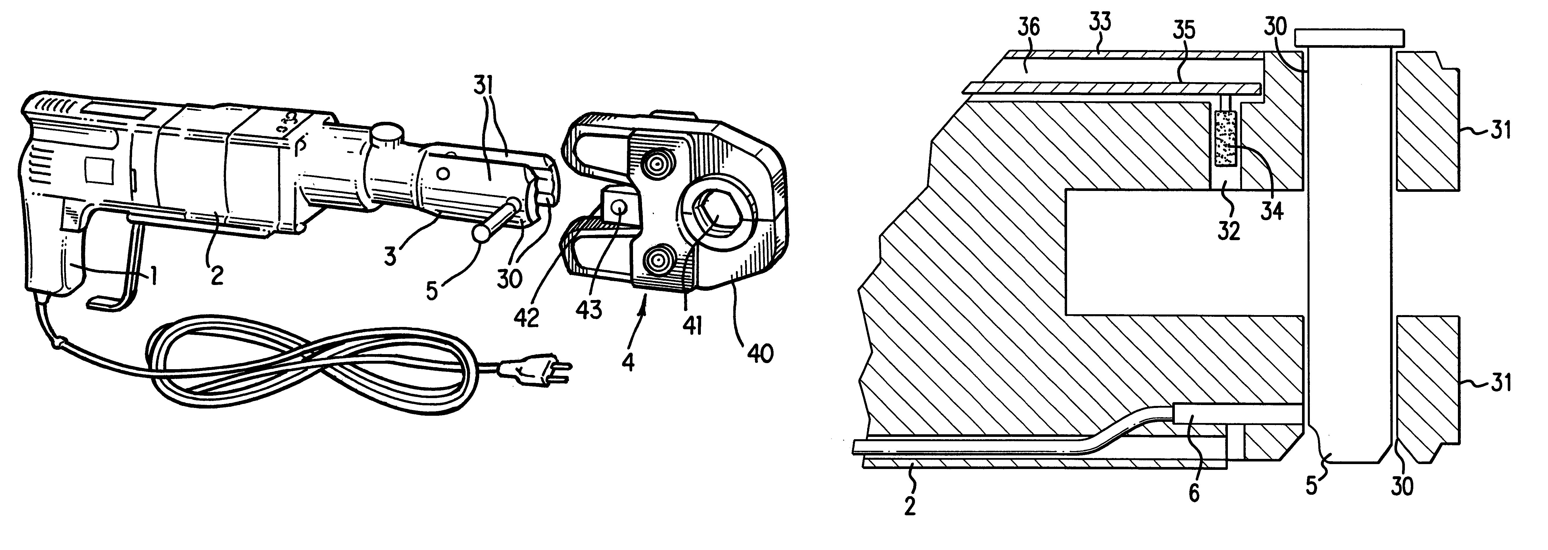
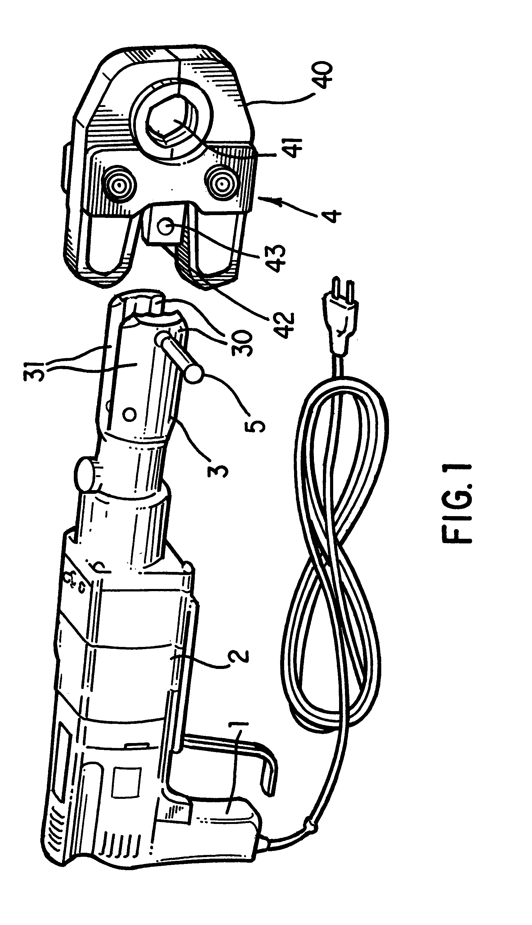
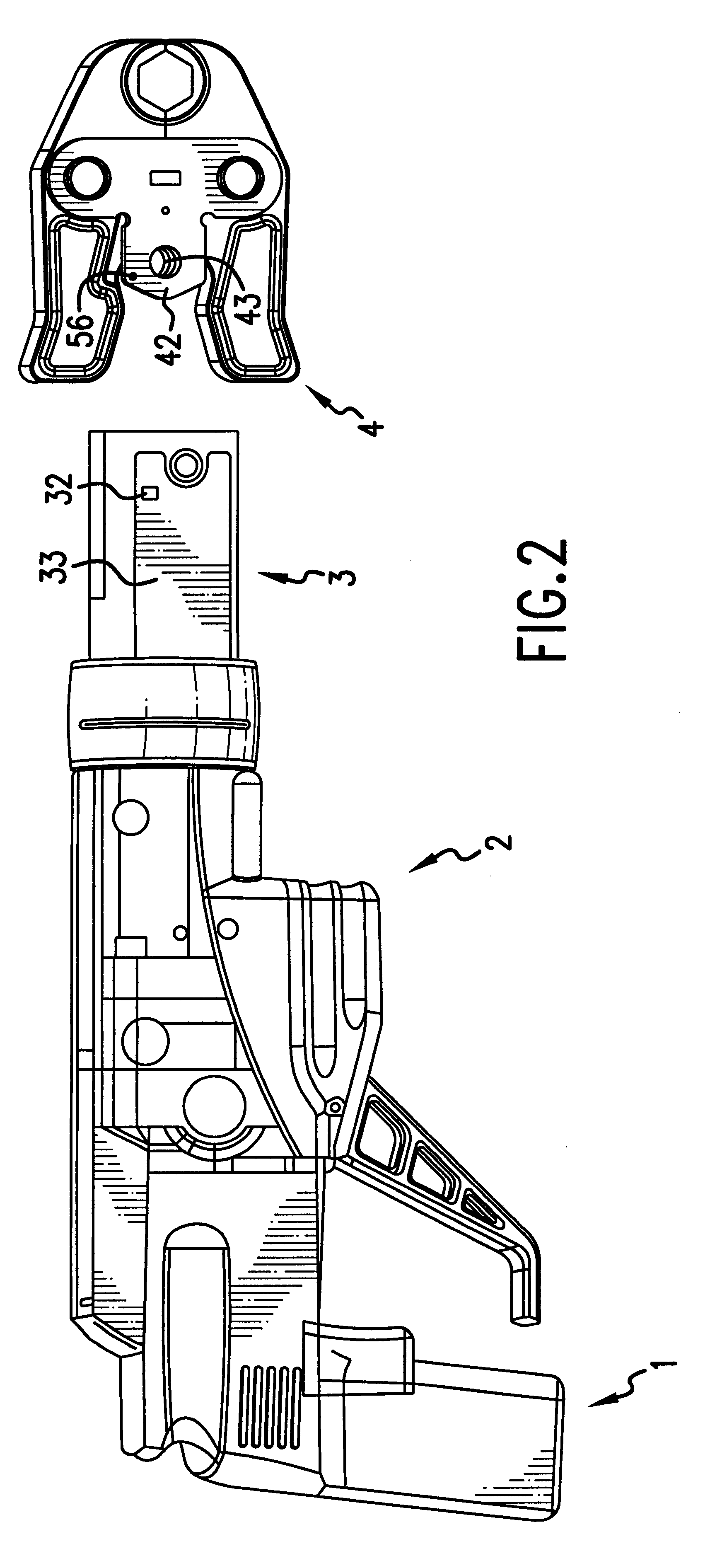
A pressing tool for pipe-shaped workpieces is shown in a perspective view in each of FIGS. 1 and 2. The pressing tool comprises an electromechanical or electro-hydraulic device, which is designed in the shape of a pistol. The device, or respectively the pressing tool, has a housing 2 with a grip 1. The pistol-shaped housing 2 terminates in a fork-shaped receiver 3 at an end remote from the grip 1. An interchangeable clamping tool 4 with two clamping jaws 40 is releasably fastened in the fork-shaped receiver 3. Together, the clamping jaws 40 form a circular opening 41 corresponding to a diameter of the workpiece to be pressed. The clamping tool 4 has two clamping jaws 40, which are securely seated between bearing plates 42, shown in detail in FIG. 4. A bore 43, extending vertically with respect to the longitudinal direction of the housing 2, extends through the bearing plates 42. In the assembled state, the bearing plates 42 are enclosed by the fork-shaped receiver 3. The fork-shaped...


PUM

PropertyMeasurementUnit
diametersaaaaaaaaaa
sizeaaaaaaaaaa
lengthaaaaaaaaaa

Abstract

A pressing tool for connecting pipe-shaped work pieces wherein the pressing tool has a fork-shaped receiver and a clamping tool interchangeably held in the receiver by a connecting bolt. The pressing tool has two clamping jaws which can be moved toward each other. A drive motor operates the clamping tool. The connecting bolt can be pushed through bores in the fork-shaped receiver and in the clamping tool, for maintaining the clamping tool in an exchangeable position within the fork-shaped receiver. A contactless electronic tracing device is arranged in the fork-shaped receiver, which determines a relative position of the clamping jaws in relation to the fork-shaped receiver. The contactless electronic tracing device also passes a signal to either an optical warning device or an acoustical warning device.

Description

1. Field of the InventionThis invention relates to a pressing tool for connecting pipe-shaped workpieces, having a fork-shaped receiver, a clamping tool, which is interchangeably held in this receiver by a connecting bolt and has two clamping jaws, which can be moved toward each other, and of a drive motor for operating the clamping tool. A connecting bolt can be pushed through bores in the fork-shaped receiver and in the clamping tool for interchangeably maintaining the clamping tool in the fork-shaped receiver.2. Description of Prior ArtPressing tools are known, which have pipe-shaped workpieces that are pressed together and two elements that are connected with each other in this way. Known cylinder-shaped workpieces are, for example, press sleeves, press fittings or connecting sleeves, as well as pipe sections, which can be pushed into each other and pressed together. These pressing tools are mostly constructed in a pistol shape and have a clamping tool. The clamping tool enclose...

Claims


Application Information

Patent Timeline
Patent Type & Authority Patents(United States)
IPC IPC(8): B25B27/02B25B27/10
CPCB25B27/10
Inventor DUMMERMUTH, PAUL
Owner VON ARX AG
Why Eureka
Try Eureka