Multi-shot, non-lethal, taser cartridge remote firing system for protection of facilities and vehicles against personnel

a technology of taser cartridges and remote firing systems, applied in the field of defensive weapons, can solve the problems of hostile persons withdrawing to a safe distance, without real-time control, and without any form of accurate aiming

Inactive Publication Date: 2001-08-07
TASER INT INC
View PDF7 Cites 57 Cited by
  • Summary
  • Abstract
  • Description
  • Claims
  • Application Information

AI Technical Summary

Problems solved by technology

However, the mine-like weapon is implemented without real time control and without any form of accurate aiming as is typical in a more conventional TASER.RTM. weapon.
Once the TASER.RTM. is fired, an inherent fear of electricity generally causes hostile persons to withdraw to a safe distance.

Method used


Image

  • Multi-shot, non-lethal, taser cartridge remote firing system for protection of facilities and vehicles against personnel
  • Multi-shot, non-lethal, taser cartridge remote firing system for protection of facilities and vehicles against personnel
  • Multi-shot, non-lethal, taser cartridge remote firing system for protection of facilities and vehicles against personnel

Examples


Embodiment Construction

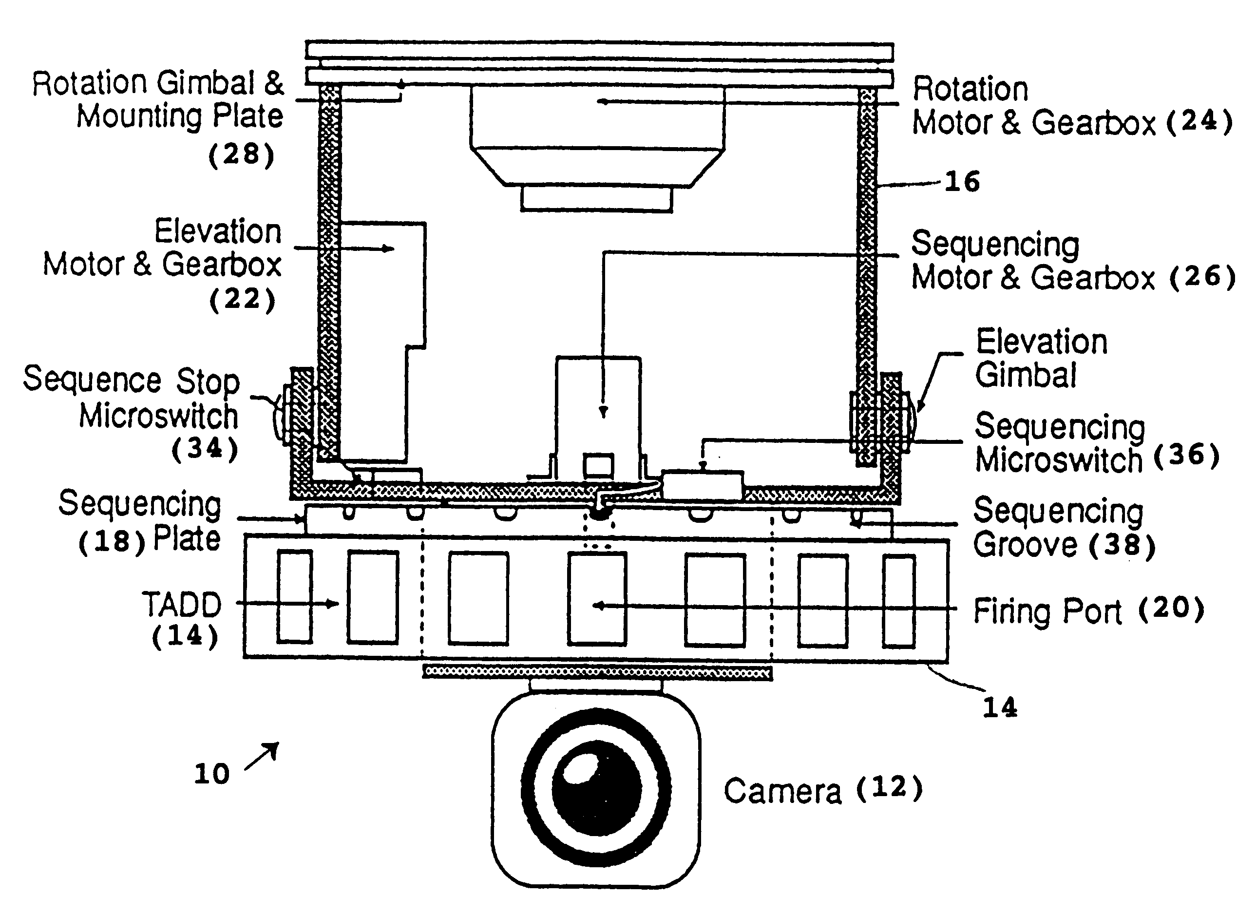
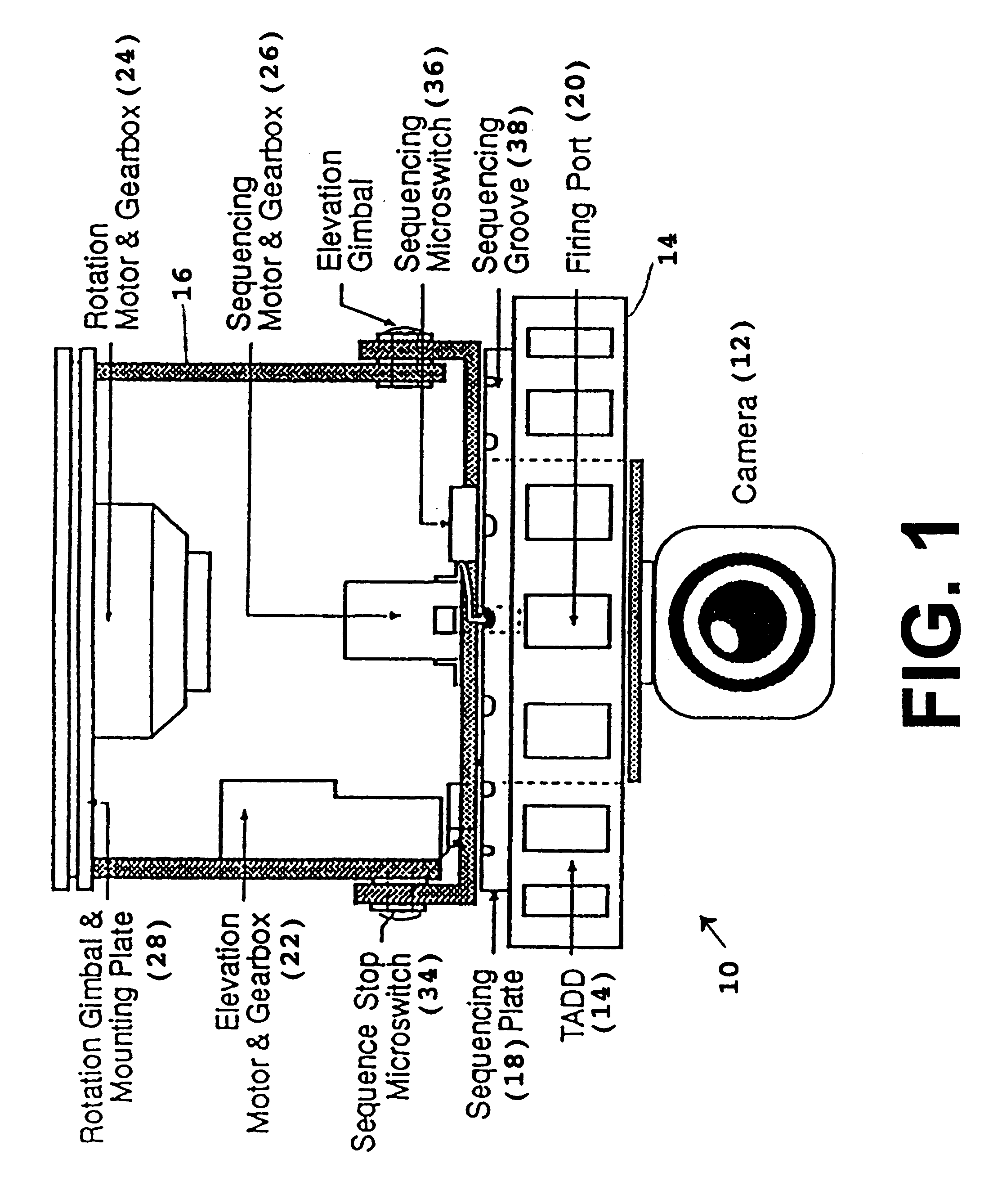
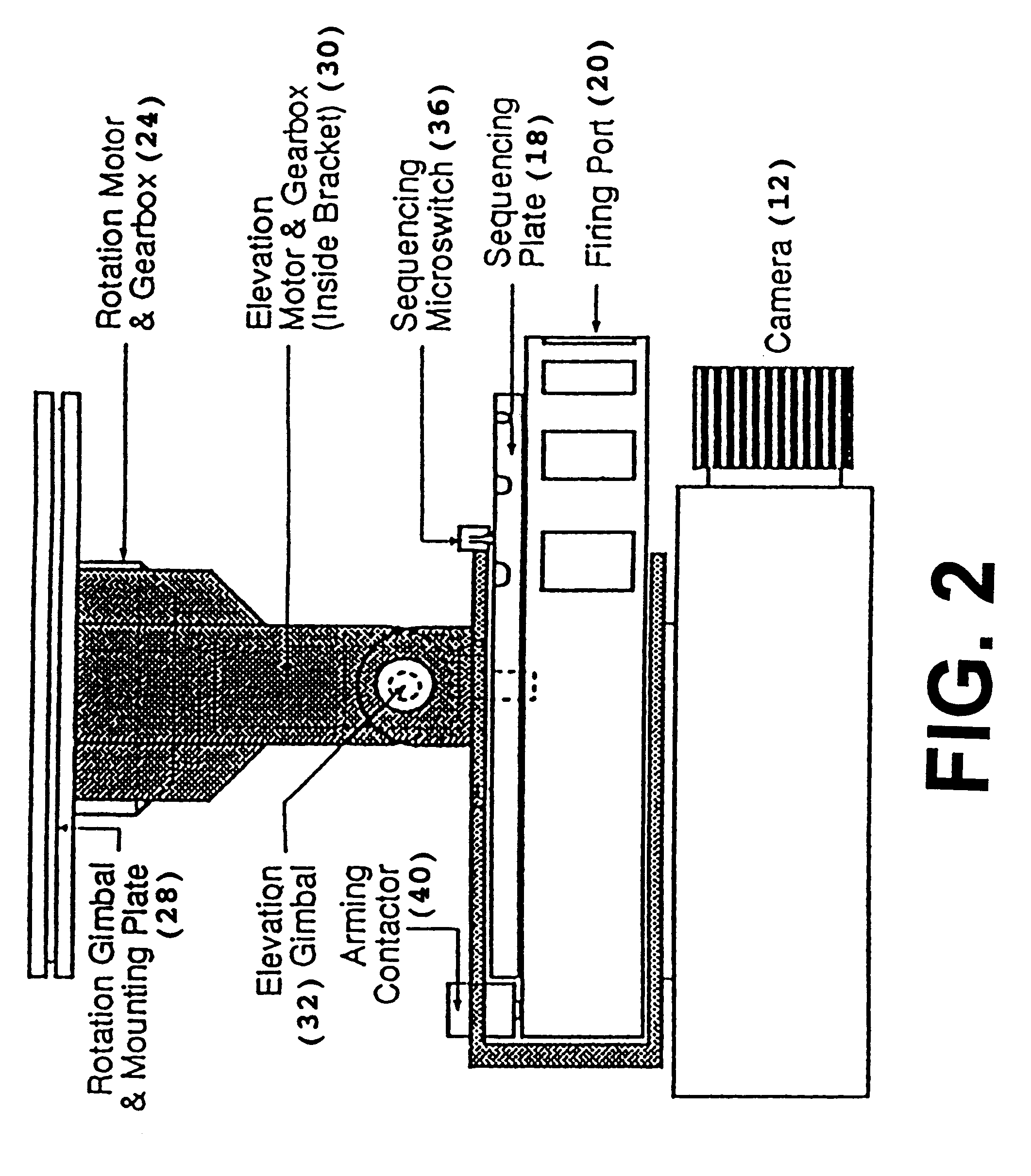
Referring to the accompanying drawings, and initially FIGS. 1-3, it will be seen that a preferred embodiment 10 of the present invention comprises three main components. These components are a camera 12, a TASER.RTM. device 14 (also referred to as TADD for TASER.RTM. area denial device) and a motion control apparatus 16. The camera 12 is preferably a real time video imaging camera with relatively good resolution up to at least 50-100 feet. The TASER.RTM. device 14 is essentially identical to that disclosed in Applicant's parent application of which this application is a continuation-in-part. However, unlike that previously disclosed TADD,TASER.RTM. device 14 has attached to it an indexing or sequencing plate 18 that automatically rotates to sequentially bring each cartridge firing port 20 into a boresight position that is aligned with the video camera boresight. In this manner, there is always one cartridge ready to be fired along the direction of the camera boresight until all of t...


PUM


Abstract

An armored, motorized unit incorporating a gimbaled gun sighted video camera and an attached multi-shot TASER(R) cartridge firing system to remotely fire one cartridge at a time at a remotely selected target. A remotely located operator rotates the unit in azimuth and elevation to aim at a target within the range of the firing system. The firing system has multiple cartridges that can be rotated into a boresight position, one at a time, and armed, one at a time, for firing a pair of wire-tethered contacts such as darts at the selected target.

Description

1. Field of the InventionThe present invention relates generally to the field of defensive weapons and more particularly to a defensive weapon comprising a multi-cartridge, remotely operated, TASER.RTM. system affixed to a video camera for remote selection of the boresight direction for cartridge activation.2. Prior ArtA non-lethal, cartridge-based TASER.RTM. weapon is disclosed in the following U.S. Pat. Nos. 3,803,463 issued Apr. 9, 1974 entitled WEAPON FOR IMMOBILIZATION AND CAPTURE; and U.S. Pat. No. 4,253,132 issued Feb. 24, 1981 entitled POWER SUPPLY FOR WEAPON FOR IMMOBILIZATION AND CAPTURE. Each cartridge comprises a pair of wire tethered contacts such as darts and a propulsion source such as gun powder, gas, or the like. The wires are connected to opposite polarities of a high voltage, low current, pulsed source of power. Upon activation of the weapon, the two darts are explosively propelled toward a selected target. Simultaneously, the high voltage is applied through the w...

Claims


Application Information

Patent Timeline
Patent Type & Authority Patents(United States)
IPC IPC(8): F42B8/00F42B8/28F42B12/02F42B12/36F41H13/00H05C1/00H05C1/04
CPCF41H13/0006F41H13/0025H05C1/04F42B12/36F42B8/28
Inventor MCNULTY, SR., JAMES F.
Owner TASER INT INC
Why Eureka
Try Eureka