Recording method using large and small dots

a recording method and small dot technology, applied in printing and other directions, can solve the problems of large size, large cost of the apparatus, and high cost of the conventional recording apparatus dedicated to photographic images

Inactive Publication Date: 2001-09-04
CANON KK
View PDF27 Cites 26 Cited by
  • Summary
  • Abstract
  • Description
  • Claims
  • Application Information

AI Technical Summary

Problems solved by technology

Conventionally, a pictorial image has been recorded by a highly sophisticated silver salt type recording apparatus which uses digital image input or an expensive sublimation type recording apparatus which is limited only to photographic output generated by using sublimation dye.
Conventional such recording apparatuses dedicated to photographic images are very expensive.
One reason is a very complicated process of the silver salt type and a large size unsuitable for desk-top use.
Another reason is use of sublimation dye by the sublimation type apparatus, which results in a larger cost of the apparatus and its larger running cost as the size of recording medium becomes larger.
These conventional recording apparatuses are too expensive for general users.
The most significant disadvantage is that design of such apparatuses assumes use of specific recording medium.
Therefore, these apparatuses are not suitable for use shared by general persons and professionals.
It is very cumbersome and difficult to discriminately use between plain paper sheets and specific recording sheets in order to record graphic originals formed by a word processor and pictorial photographic originals.
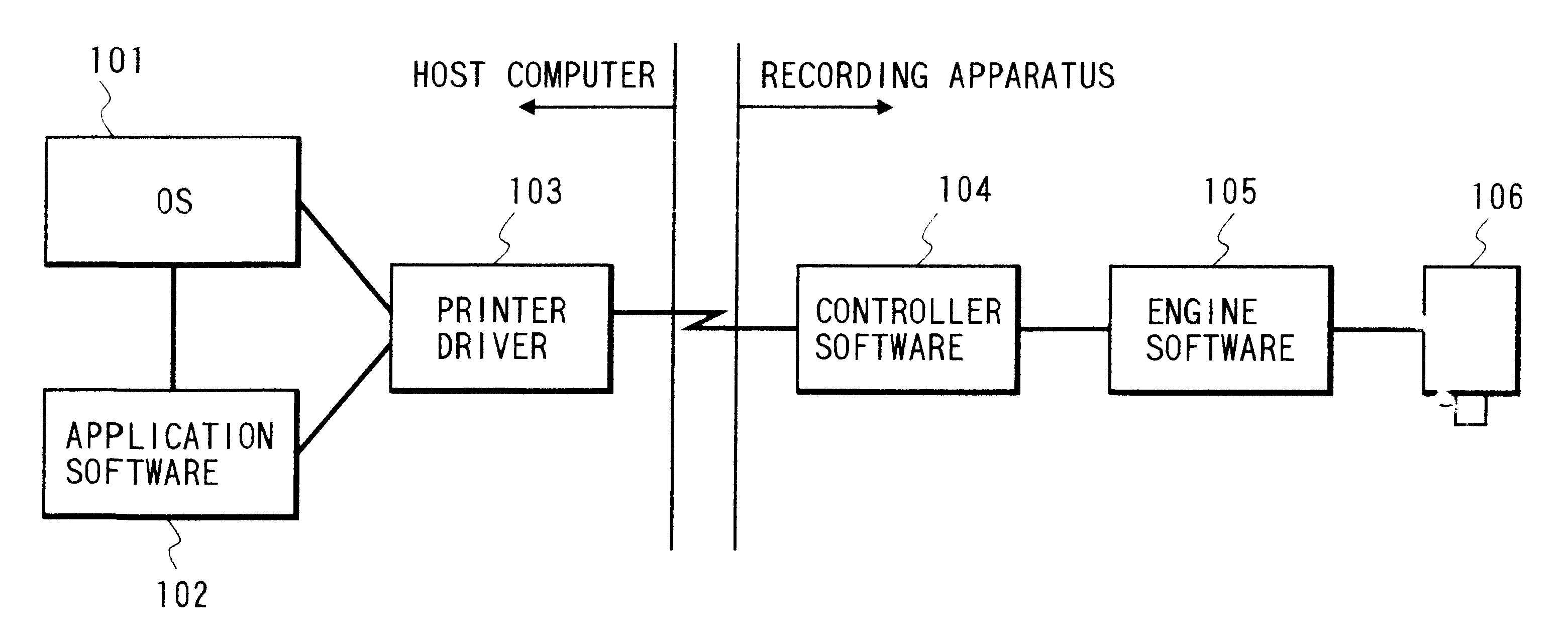
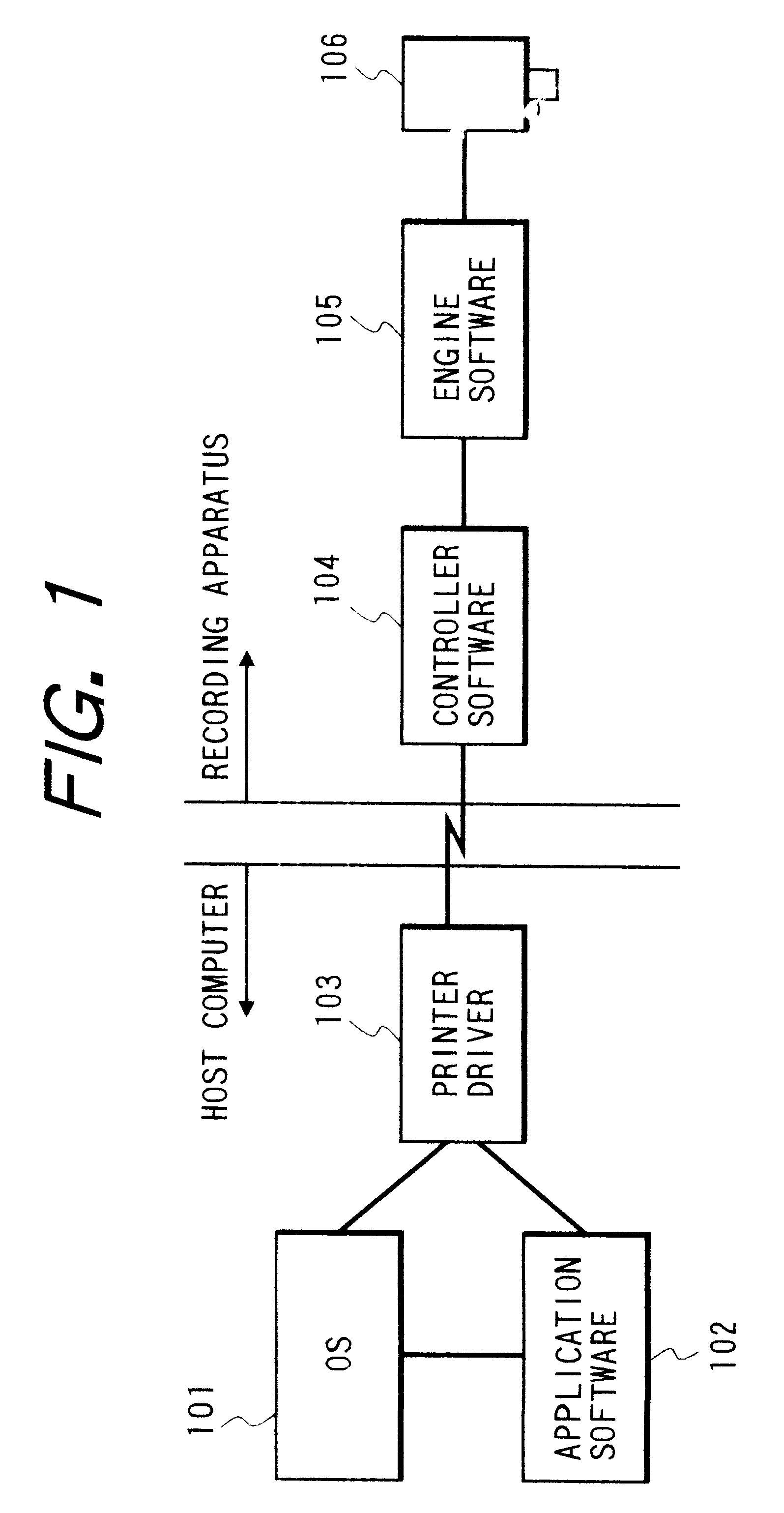
(1) The method of uniformly reducing ink jet amount records an image at a higher resolution both in the main and subsidiary scan directions. Therefore, the number of main scans increases and the feed amount in the sub-scan direction reduces so that the recording speed lowers greatly. As the resolution of recording data is raised, the data amount increases greatly which results in a large increase of the memory capacity, increased data transfer amount and time required by interface, an increase of load of a printer driver, and the like. For example, if the resolution of record data is increased by two times, the data amount is doubled for both in the main and sub-scan directions so that the total data amount is a square of 2 or four times. Since recording dots are made fine in order to suppress a granular image quality (irregular image quality) at a low density area, a number of fine dots are also recorded at the high density area although in this area the granular image quality does not become conspicuous. Although the total image quality can be improved, an image forming efficiency is not improved correspondingly.
(2) Another recording method is to use a combination of large and small dots. This method can improve an image forming efficiency. This method can be applied easily if one recording nozzle is used for each color. However, if a plurality of nozzles are used for each color, this method becomes difficult as the number of nozzles increases. Ejection of ink droplets from each nozzle is generally performed at several KHz or higher. If the number of nozzles is small, these nozzles can be controlled directly by a CPU. However, as the number of nozzles increases, it becomes necessary to use hardware such as gate array circuits in addition to the operation of CPU in view of a processing speed. In order to modulate the ink ejection amount of large and small dots, either an ejection drive pulse is modulated or an ejection drive element in a nozzle is changed.
The number of necessary registers is an integer multiple relative to a record resolution so that the circuit scale of the recording head becomes large and the cost of the recording head rises.
In this case, other elements such as signal line contacts, a flexible cable to the recording head, recording element driver transistors and the like are also required, leading to increased cost.
Recording under these conditions may result in a wasteful scan if there is no large dot to be recorded because of small dots recorded at all available lattice points.
In addition to this problem, the prevention effect of so-called banding which is characteristic to the multi-path divisional recording is lost, because the recording is performed 100% only by small dots during one scan of the two-path scans.
Still further, since the record ratio between scans is not uniform, several problems occur such as an inability of lowering an error rate during a scan with a higher record ratio because of different record ratios, an inability of lowering consumption power because of a high instantaneous power during a scan with a higher record ratio, and the like.

Method used


Image

  • Recording method using large and small dots
  • Recording method using large and small dots
  • Recording method using large and small dots

Examples


second example

In the first example, a plurality of dots including large and small dots are used in accordance with the gradation of pixel data for recording pixel data represented by two bits. In the first example, the importance of the record order of large and small dots is not specifically described. However, it is known that the positions of small and large dots ejected from nozzles and recorded on recording medium shift slightly. Therefore, the record positions of small and large dots during one record scan of the recording head displace although this displacement is minute, so that a texture or the like may be formed on the recorded image.

FIGS. 26A to 26C show examples of recorded dots while the recording head is moved from the right to left as viewed in FIGS. 26A to 26C, and illustrate a displacement of recorded small and large dots caused by an ejection speed difference.

In FIG. 26A, timings indicated by solid lines represent true record positions of large dots, and timings indicated by br...


PUM


Abstract

An ink jet recording apparatus and method for recording an image on a recording medium by ejecting ink from each of a plurality of recording elements of a recording head is provided. The apparatus includes an ink ejection amount changing unit for changing an ink ejection amount of each recording element of the recording head, a timing controller for controlling an ink ejection timing of the ink ejection amount changing unit, a modulator for modulating record data, and a controller for controlling to record an image on the recording medium by outputting the record data modulated by the modulator synchronously with an ejection timing determined by the timing controller.

Description

1. Field of the InventionThe present invention relates to an ink jet recording method and apparatus and an ink jet recording head, in which recording is preformed by ejecting ink out of a recording head and applying it to recording medium.2. Related Background ArtIn recording apparatuses such as printers, copiers, and facsimiles, dots are recorded with recording elements (such as nozzles, heating elements and wires) on recording medium such as paper and plastic thin plate in accordance with image information to thereby record an image composed of dots. Such recording apparatuses are classified based on their recording methods, into an ink jet type, a wire dot type, a thermal type, a laser beam type, and the like. Of these types, the ink jet type (ink jet printer) records an image by ejecting ink (recording liquid) out of an ejection port (nozzle) of a recording head and blowing it onto recording medium.A number of recording apparatuses are used nowadays with output terminals such as...

Claims


Application Information

Patent Timeline
Patent Type & Authority Patents(United States)
IPC IPC(8): B41J2/05B41J2/205B41J2/175B41J2/21B41J2/01
CPCB41J2/04533B41J2/0458B41J2/04593B41J2/2128B41J2/1752B41J2/2054B41J2/17513B41J2/04
Inventor OTSUKA, NAOJITAKAHASHI, KIICHIRONISHIKORI, HITOSHIIWASAKI, OSAMUKOITABASHI, NORIBUMI
Owner CANON KK
Why Eureka
Try Eureka