Method and apparatus for remotely changing signal characteristics of a signal generator

a signal generator and signal characteristic technology, applied in the direction of fault location, measurement devices, instruments, etc., can solve the problems of reducing the number of possible solutions, process almost always fails, and often equal tone output of the receiver

Inactive Publication Date: 2001-11-27
JOHN FLUKE MFG CO INC
View PDF6 Cites 95 Cited by
  • Summary
  • Abstract
  • Description
  • Claims
  • Application Information

AI Technical Summary

Benefits of technology

While this invention can be used in a stand-alone signal generator / detector whose sole purpose is to generate this tone signal and respond to indications from its detector, the preferred approach is to employ the invention in a more versatile device such as a multimeter or TDR that contains among other elements a versatile signal generator, a detector, and a control circuit that directs the operation of the device. In such a preferred embodiment, this invention can be implemented totally in the software of the control circuit at minimal or even no additional cost.

Problems solved by technology

While this process often works well, it fails when the wires are in sufficient proximity for the injected signal to couple across to one or more of them.
In that case, the tone output of the receiver is often equally loud when placed near many of the wires and identification is not possible.
In the not so simple case where the known end of the wires is already bundled in a large quantity of wires, and this bundle along with other bundles are routed in close proximity for a long length, the process almost always fails, allowing a tone to be produced from the signal on many of the wires.
While this failed process has often reduced the count of possible solutions, it sometimes does not.
This is clearly an inefficient process.
There exist expensive and complex devices that allow for the remote changing of the injected signal but require special instrumentation at the remote end.
These existing methods and devices require specific and expensive pieces of test equipment that may be justified for use by test technicians, but are not generally in the possession of ordinary households.

Method used


Image

  • Method and apparatus for remotely changing signal characteristics of a signal generator
  • Method and apparatus for remotely changing signal characteristics of a signal generator
  • Method and apparatus for remotely changing signal characteristics of a signal generator

Examples


Embodiment Construction

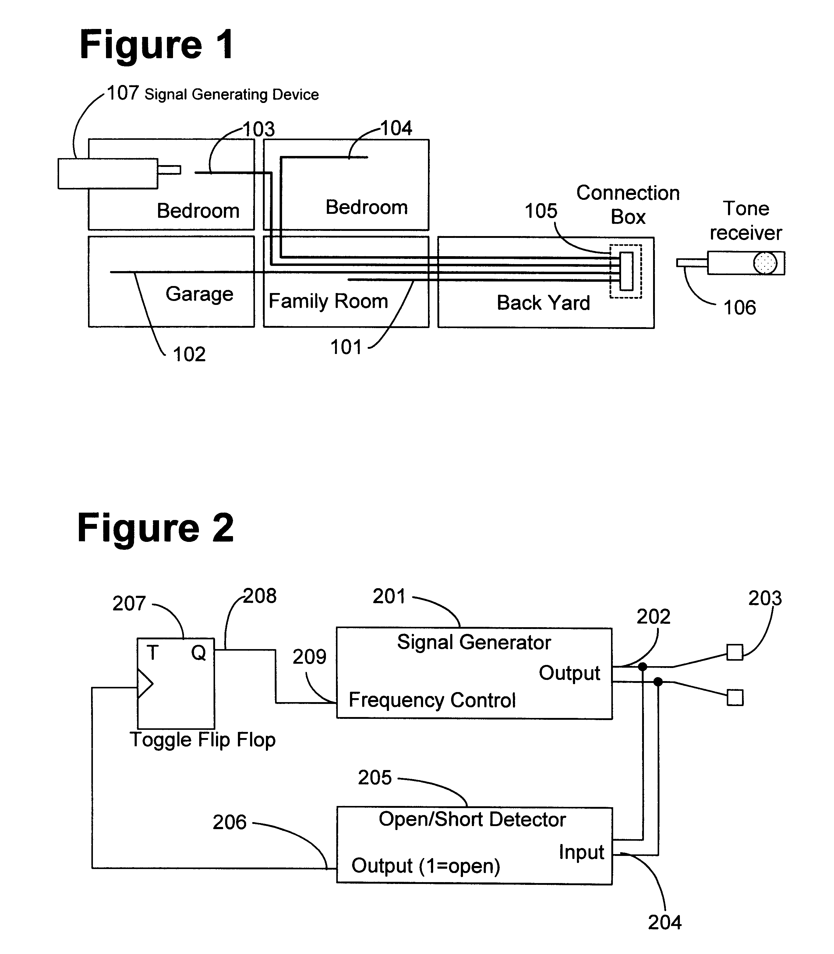
FIG. 1 illustrates a simple, typical household wiring or cable installation. Each room is wired separately to a common connection box located in the back yard. Utilizing the principles of the present invention the installer could place the signal generator 107 on wire 103 in the upstairs front bedroom and then travel down to the back yard connection box 105. With his or her receiver 106, the individual could probe each of the four wires at that connection box to try and determine which of the cables extends from the upstairs front bedroom. When all four of the cables cause approximately the same tone indication (as would often be the case), he or she could then sequentially short and open each pair of wires until the characteristics of the tone change. At that point, there would be positive identification of the wire pair.

In FIG. 2, a stand-alone embodiment of the invention is illustrated. A versatile signal generator 201 couples its output 202 to the cable connection 203 and to the...


PUM


Abstract

A detector and a variable signal generator are coupled so that one or more specific changes in the output of the detector will cause a change in the characteristics of the generated signal. This change in signal characteristics is non-transient, the change remaining in effect until such time that another change in the detector output causes another change in the signal characteristic. The system can provide remote-end positive wire identification with no additional instrumentation at the remote end. When this invention is embodied in an already existing piece of test equipment, such as a multimeter or time domain reflectometer, there need be no additional hardware instrumentation at either end.

Description

This invention relates to remote changing of the characteristics of a signal produced by a signal generator. This invention has particular application to locating or identifying one or more electrical conductors such as household wiring, commercial wiring, and industrial wiring installations. Examples of such wiring are TV coax and antenna wires, all types of electrical wires, telephone and data wires, environmental control wires, etc. No instrumentation is needed at the remote end of the wiring under test to effect the change in signal characteristic.Many devices exist that inject a signal onto a length of wire or pair of wires for the purpose of physically locating other parts of the length thereof. These devices are commonly called `tone generators`, even though these devices themselves only produce an electrical signal and a receiver functions to produce the actual audible tone. U.S. Pat. No. 5,457,441, for example, discloses a receiver of the inductive pick-up type which produc...

Claims


Application Information

Patent Timeline
Patent Type & Authority Patents(United States)
IPC IPC(8): G01R31/02G01R31/50
CPCG01R31/024G01R31/50
Inventor NEEDLE, DAVID L.SHEPARD, STAN F.GIN, GARY
Owner JOHN FLUKE MFG CO INC
Why Eureka
Try Eureka