Combine straw and chaff spreader

Inactive Publication Date: 2002-02-05
SAGE CREEK COLONY
View PDF10 Cites 44 Cited by
  • Summary
  • Abstract
  • Description
  • Claims
  • Application Information

AI Technical Summary

Benefits of technology

A straw and chaff spreader includes a pair of counter-rotating spreader plates having fan-shaped blades attached to the top surface of each spreader plate. The spreader plates are located beneath the straw and chaff chute of a combine. A rear shield is mounted to the combine to the

Problems solved by technology

These windrows create problems for farmers who generally have to use other equipment for spreading or collecting the straw to remove the windrows.
With this equipment,

Method used


Image

  • Combine straw and chaff spreader
  • Combine straw and chaff spreader
  • Combine straw and chaff spreader

Examples


Embodiment Construction

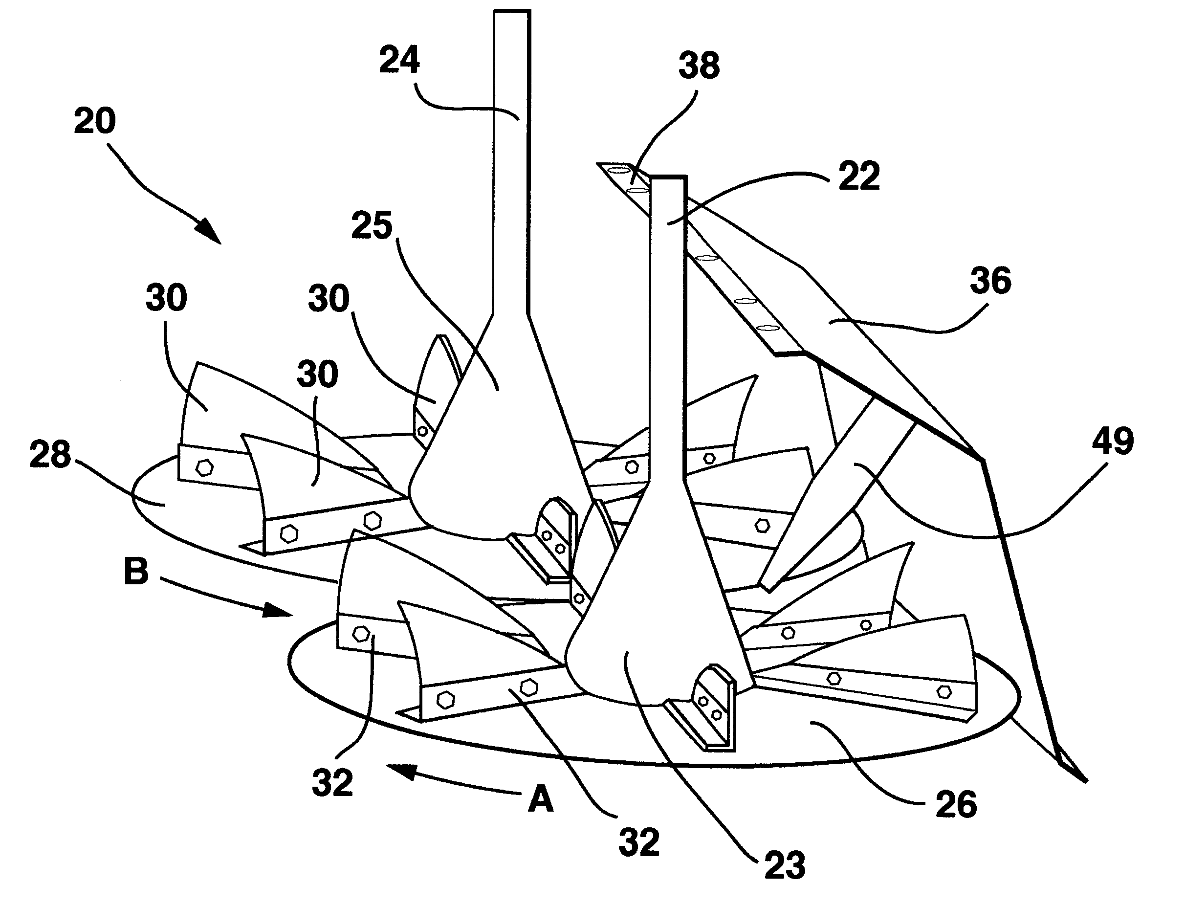
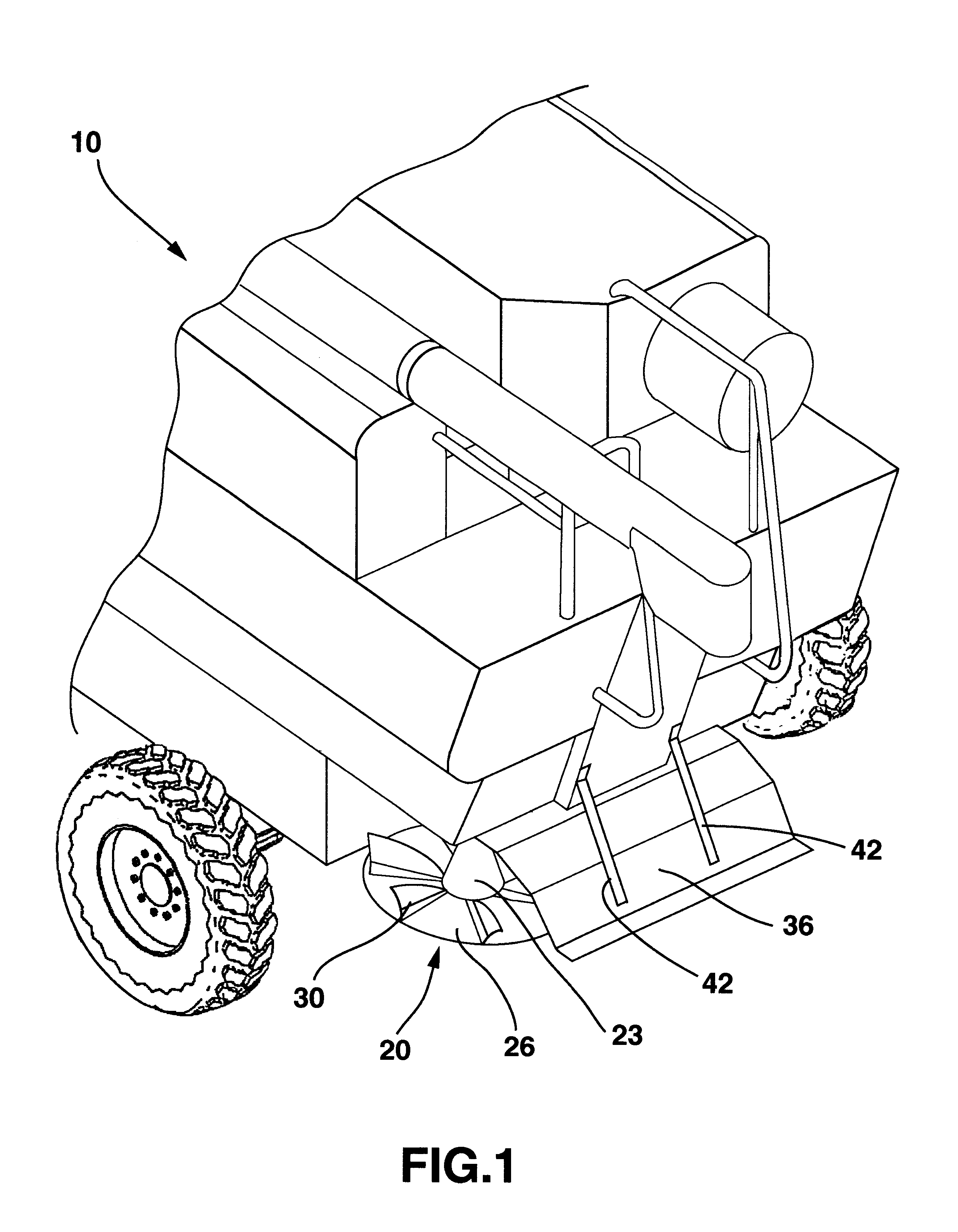
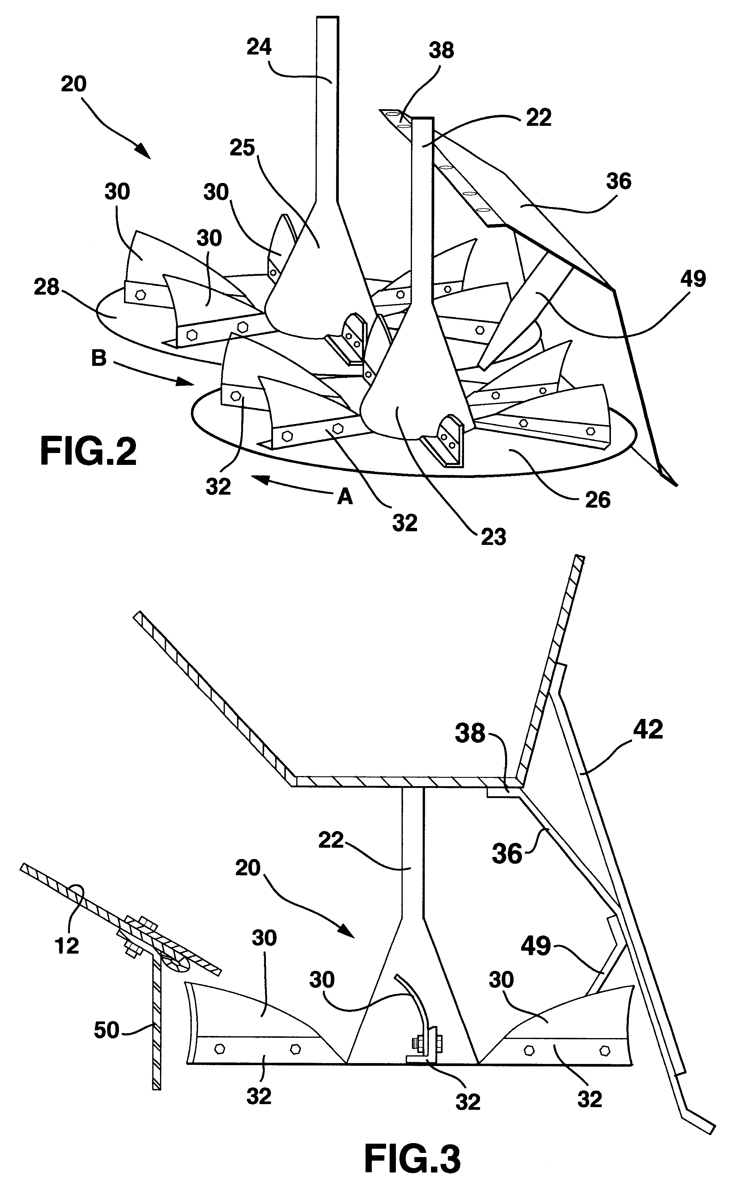
A conventional harvester combine 10 is shown in FIG. 1 with a straw and chaff spreader 20 according to the present invention attached to the rear of the combine beneath a conventional straw and chaff chute 12 of the combine 10 as shown in FIG. 3. With reference to FIG. 2, the spreader 20 includes conventional counter-rotating shafts 22 and 24 which are connected to and driven by the combine 10 in a conventional manner. The shafts 22 and 24 are secured, as by welding, to conical axle linkages 23 and 25 respectively. The conical linkages 23 and 25 are secured as by welding to a conventional left spreader plate 26 and a conventional right spreader plate 28 respectively. Spreader plate 26 is rotated in a clockwise direction indicated by arrow "A" and spreader plate 28 is rotated in a counterclockwise direction indicated by arrow "B" by conventional driving equipment used with the combine.

According to the present invention, slinger blades 30 are mounted to the conventional spreader plate...


PUM


Abstract

A straw and chaff spreader including a pair of counter-rotating spreader plates having fan-shaped blades attached to the top surface of each spreader plate. The spreader plates being located beneath the straw and chaff chute of a combine. A rear shield is mounted to the combine to the rear of the spreader plates. The shape of the blades and the direction of rotation of the spreader plates being selected to throw the straw and chaff received from the straw and chaff chute against the rear shield to propel the straw and chaff outwardly on either side of the combine.

Description

The present invention relates to a straw and chaff spreader for use with a combine to broadcast straw and chaff to the rear and opposite sides of the combine after the threshing operation.When a conventional combine is used for harvesting grain, such as wheat, the combine machine first cuts the wheat and conveys the stalks and wheat heads upwardly into the combine. A threshing mechanism is used to separate the grain from the wheat stalk. The grain is then conveyed by the combine to a series of sieves where the chaff is blown away from the grain by blasts of air. The grain separated from the chaff is then conveyed within the combine to a grain chute while the straw stalks and chaff are typically conveyed or blown rearwardly to fall upon the ground through a rear straw and chaff outlet chute. In the absence of some mechanism for spreading the straw and chaff, the straw and chaff typically falls into a windrow trailing behind the combine harvester. These windrows create problems for fa...

Claims


Application Information

Patent Timeline
IPC IPC(8): A01D41/00A01D41/12A01F29/12
CPCA01D41/1243
Inventor HOFER, DAVID A.
Owner SAGE CREEK COLONY
Why Eureka
Try Eureka