Flip top cap with tamper evident flap

a flap and flap technology, applied in the direction of closure lids, closure stoppers, liquid dispensing, etc., can solve the problems of inconvenient return of products, inconvenient for consumers to return products, and much more troublesome for retailers to accept returns

Inactive Publication Date: 2002-02-19
PANO CAP CANADA
View PDF16 Cites 45 Cited by
  • Summary
  • Abstract
  • Description
  • Claims
  • Application Information

AI Technical Summary

Problems solved by technology

One of the difficulties with the prior art closure is that the diaphragm is located within the closure itself.
If there is evidence that the diaphragm has been tampered with, it ...

Method used


Image

  • Flip top cap with tamper evident flap
  • Flip top cap with tamper evident flap
  • Flip top cap with tamper evident flap

Examples


Embodiment Construction

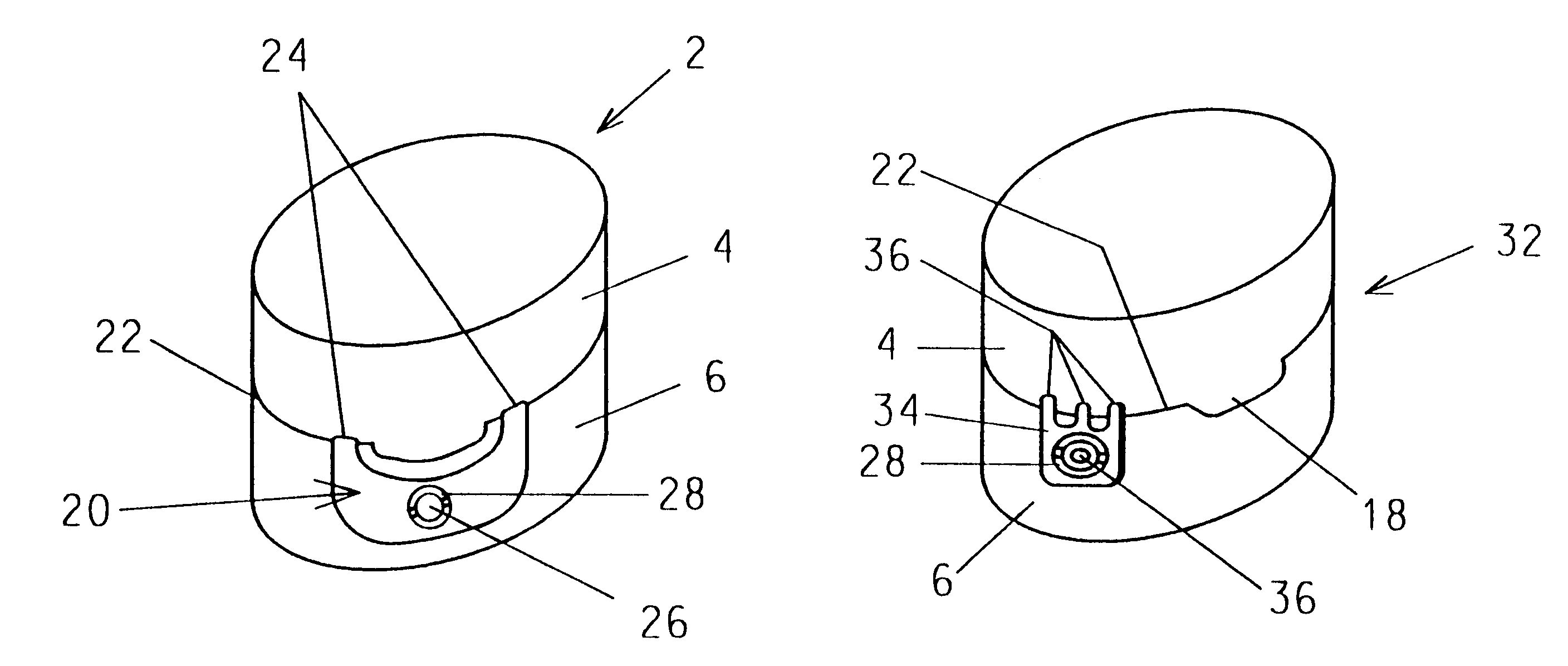
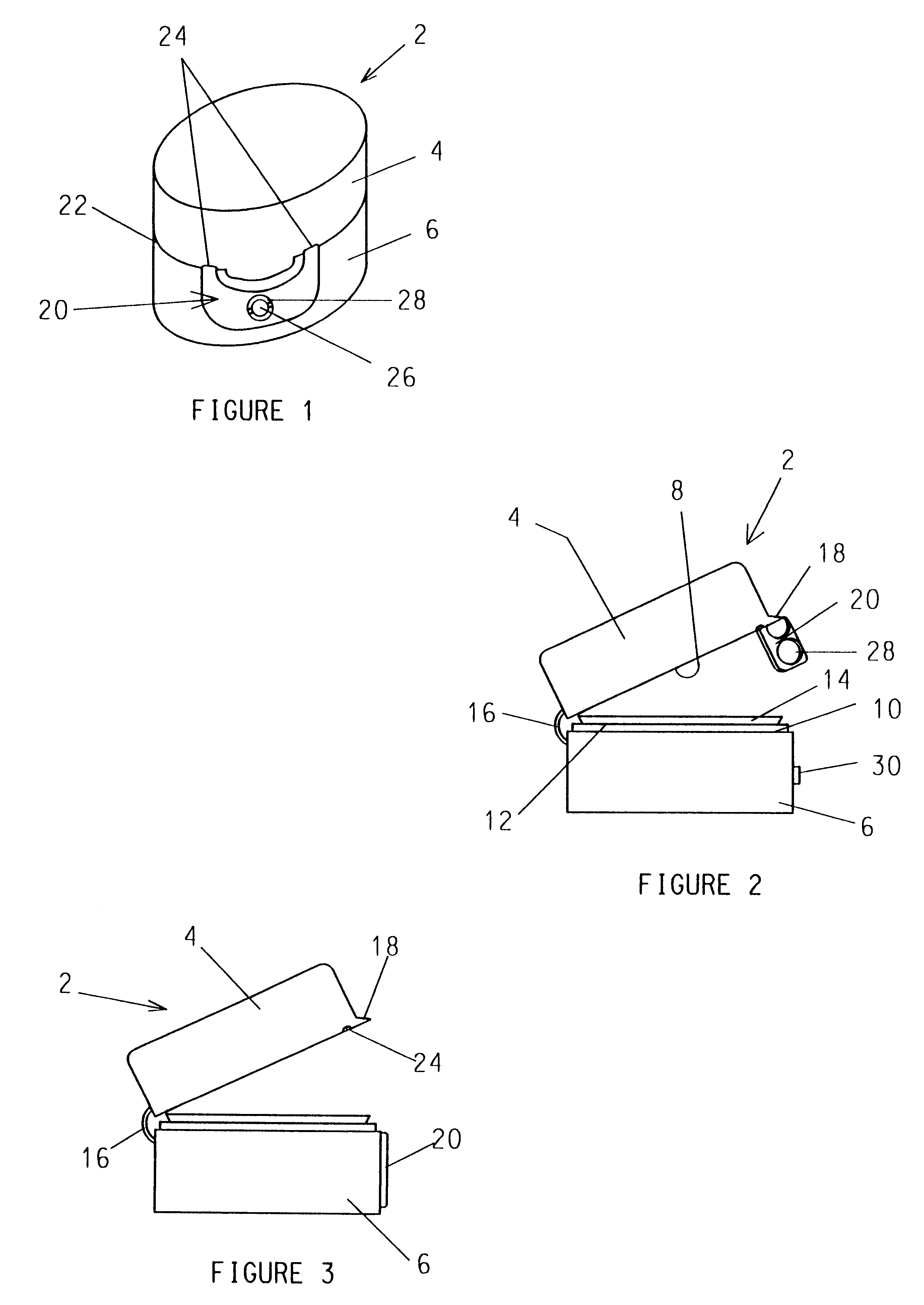
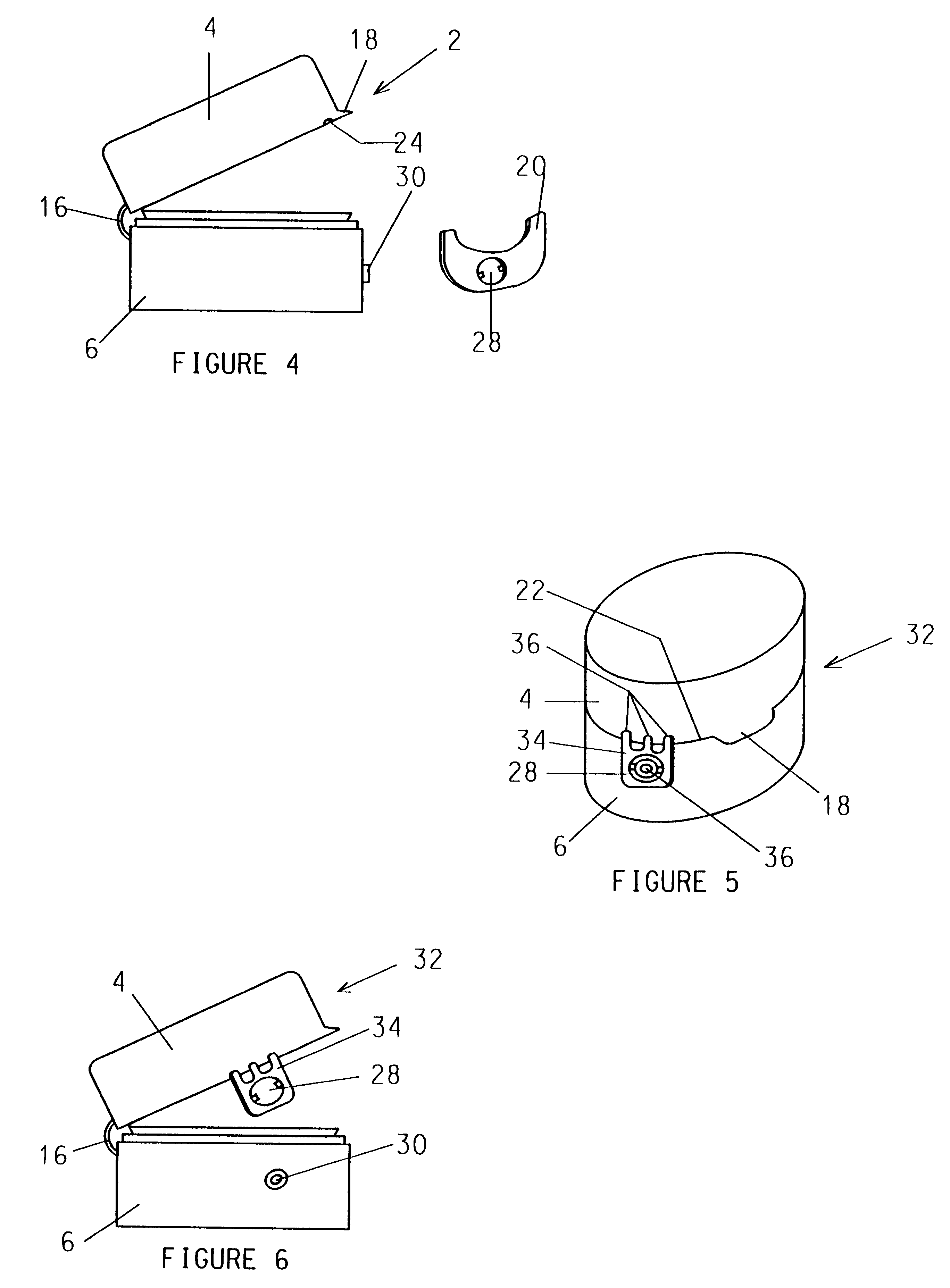
In FIGS. 1 to 4, there is shown a tamper evident flip top pouring closure 2 having an upper section 4 and a base section 6. The sections 4, 6 each have a periphery with lips 8, 10 respectively as best shown in FIG. 2. The base section contains a vertical wall 12 located immediately inside of said lip 10 and seal 14 to receive a corresponding seal (not shown) within the upper section 4. The sections 4, 6 are affixed to one another by a hinge 16. An interior of the closure is conventional. The sealing diaphragm can be included in the interior of the closure, but is preferably omitted as it is not required as a tamper evident feature.

The lip 8 of the upper section 4 has an extension 18 thereon as best shown in FIG. 3 to provide gripping means for a finger of a user when it is desired to open or close the closure. When the closure is in a closed position as shown in FIG. 1, a flap 20 extends across a line of contact 22 and is affixed to the upper section 4 by hinges 24 and to the base s...


PUM


Abstract

A flip top closure has a tamper evident flap and is used on a container with a neck and an opening therein. the neck has an outer surface with retaining means for the closure thereon. The closure has two sections that are hinged to one another and with each section having a lip extending along an edge thereof. When the closures are in a closed position, the two lips form a continuous line of contact with one another and a flap extends across the line of contact. The flap is connected to one section by ultrasonic spot welding. The flap is severable from either or both sections. When the closure is opened the flap separates from one of the sections.

Description

1. FIELD OF INVENTIONThis invention relates to a flip top closure with a tamper evident flap thereon, said flap being severed when said closure has been opened.2. DESCRIPTION OF THE PRIOR ARTFlip top closures are known and it is known to have tamper evident flip top closures where a diaphragm is located inside the closures, the diaphragm being connected to a finger loop so that the diaphragm can be removed. One of the difficulties with the prior art closure is that the diaphragm is located within the closure itself. When consumers are purchasing products containing the flip top closure, they often do not lift the flip top before completing the purchase. Upon arriving at their residence, consumers will likely not open the flip top until such time as they wish to begin to use the product within the container. At that stage, the consumer observes for the first time the diaphragm within the flip top closure. If there is evidence that the diaphragm has been tampered with, it is extremely...

Claims


Application Information

Patent Timeline
IPC IPC(8): B65D47/10B65D47/06B65D47/08
CPCB65D47/103B65D47/0804
Inventor NOFER, KARL H.KRAJNC, JOZEF
Owner PANO CAP CANADA
Why Eureka
Try Eureka