Brake actuator

a technology of brake actuator and actuator, which is applied in the direction of brake cylinder, braking system, machine/engine, etc., can solve the problems of diaphragm wear, leakage between the pneumatic chamber and the brake actuator, and diaphragm wear

Inactive Publication Date: 2002-02-26
INDIAN HEAD INDUSTRIES INC
View PDF4 Cites 43 Cited by
  • Summary
  • Abstract
  • Description
  • Claims
  • Application Information

AI Technical Summary

Problems solved by technology

A problem with any diaphragm-type brake actuator is diaphragm wear.
The synthetic rubber surfaces, however, wear during normal operation of the brake actuator, potentially resulting in leakage between the pneumatic chambers of the brake actuator.
However, when the cup-shaped diaphragm is inverted to actuate the vehicle braking system as shown in FIG. 1 and during return of the diaphragm to its extended cup-shape, the contact surface 52 is spaced from the central portion 36 of the diaphragm and the outer edge 54 of the piston rubs against the inside surface of the diaphragm as the diaphragm is inverted, resulting in frictional wear.
This problem can be reduced by gluing the contact surface of the piston to the central portion of the diaphragm to prevent separation of the piston and the diaphragm; however, gluing or adhesive bonding is expensive and creates separate problems, including handling and disposal problems.
Further, a brake actuator must be able to withstand extreme temperature and humidity variations during normal operation and the adhesive may fail.
Further, the diaphragm in the spring chamber inverts under greater force because it is driven by the power spring resulting in greater wear of the diaphragm in the spring chamber.

Method used


Image

  • Brake actuator
  • Brake actuator
  • Brake actuator

Examples


Embodiment Construction

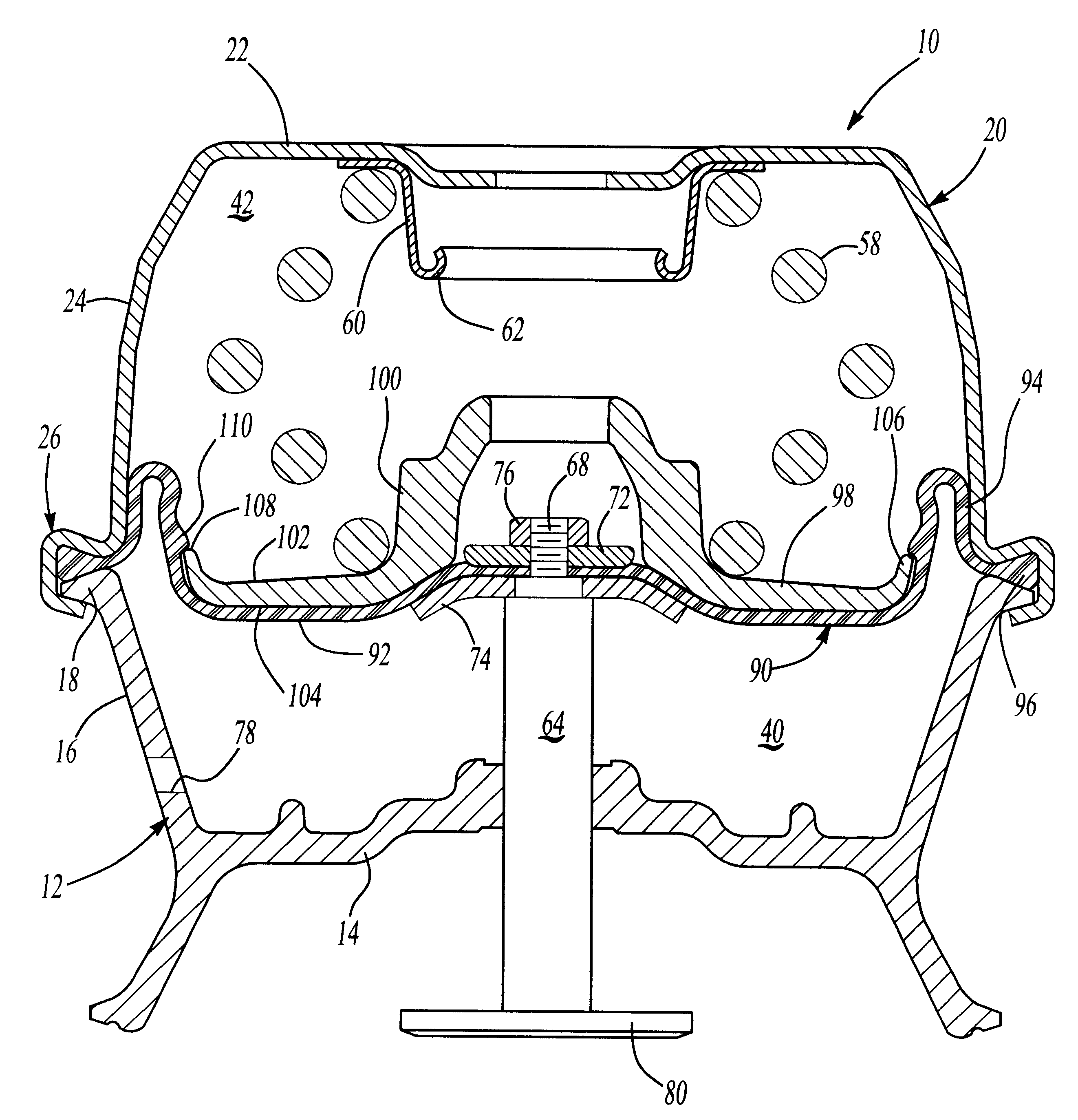
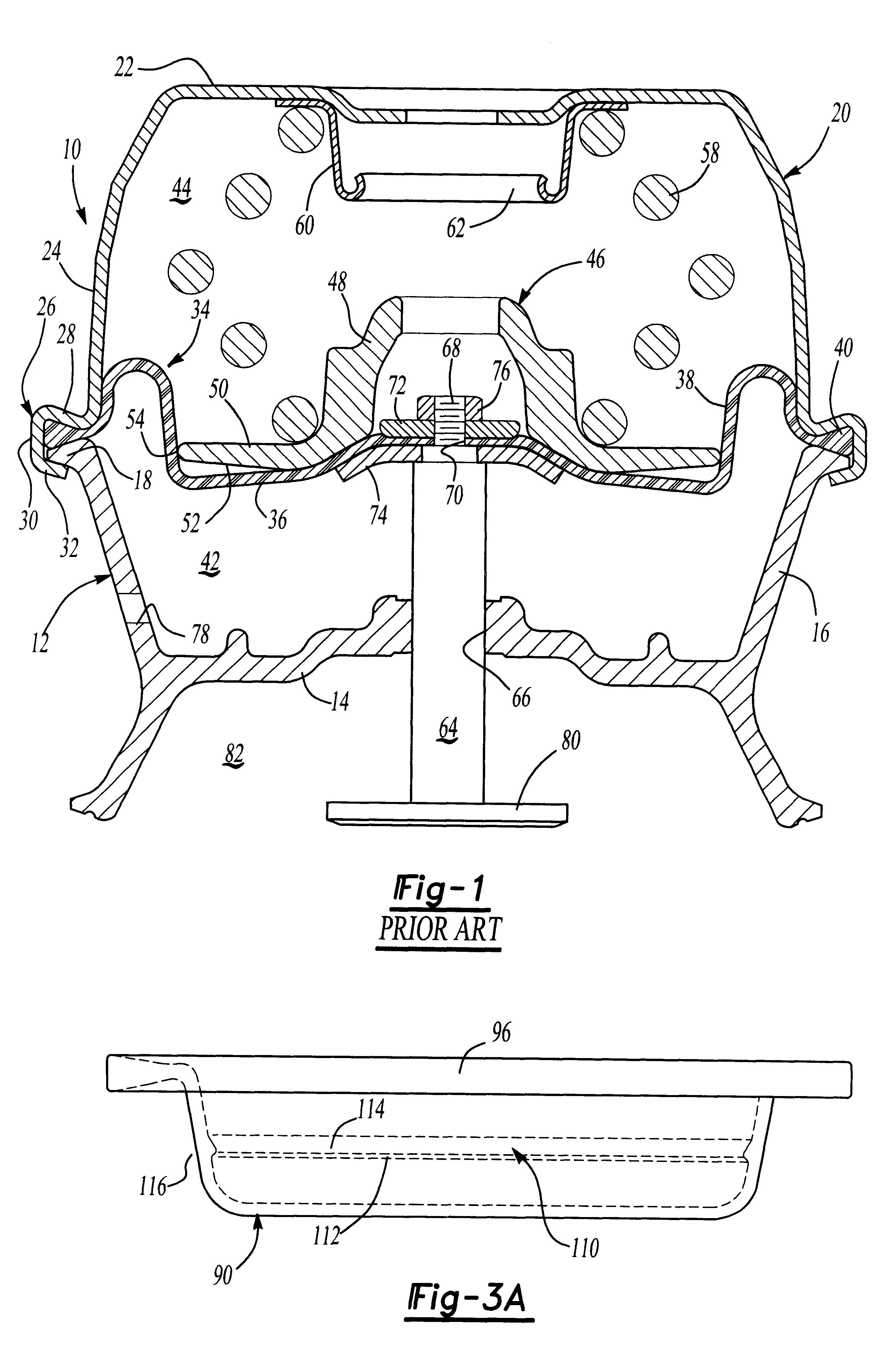
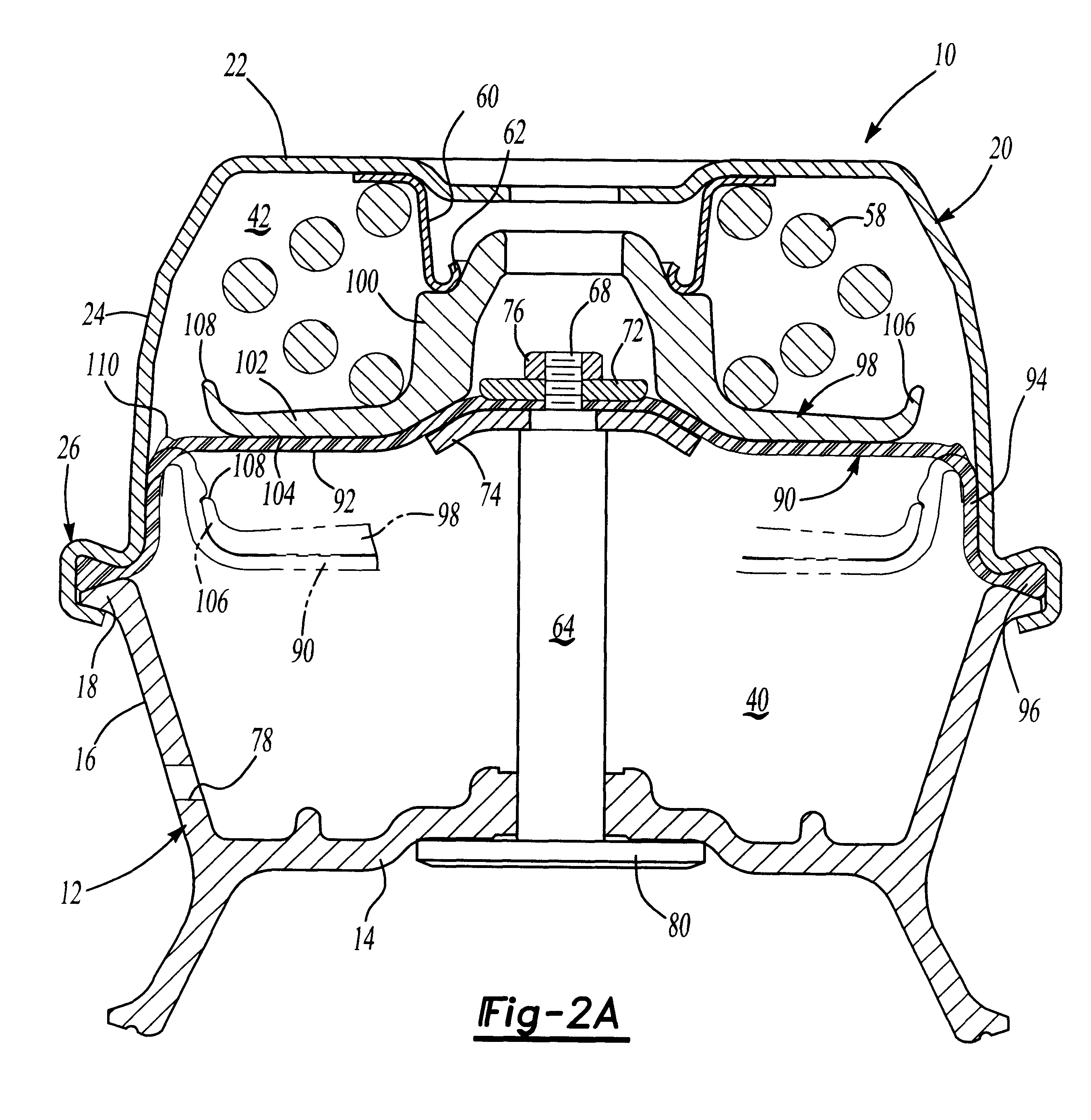
As set forth above, the general construction of the improved pneumatic brake actuator for a vehicle braking system of this invention may be conventional. That is, the improved mechanical interlock between the piston and the diaphragm may be utilized with conventional diaphragm-type brake actuators. FIG. 2A illustrates a spring brake actuator or chamber 10, as illustrated in FIG. 1 described above, including a flange case 12, a cover or head 20, a power spring 58 and a push rod 64. No further description of these components which are common to the conventional spring brake actuator shown in FIG. 1 are necessary.

In FIG. 2A, The flexible diaphragm 90 is in the extended cup-shaped position, ready for installation in the brake actuator. As shown and described above, the diaphragm includes a central portion 92, a side wall 94, which is generally conical, and a rim portion 96, which is received between and compressed by the flange portions 26 and 18 of the housing components forming a lowe...


PUM


Abstract

An improved diaphragm-type pneumatic brake actuator wherein the diaphragm is releasably secured to the piston as the diaphragm is inverted during actuation of the braking system of a vehicle thereby reducing wear of the flexible diaphragm and improving the performance of the brake actuator. In the disclosed embodiment, a rib or lip is formed on the surface of the diaphragm which receives the periphery of the piston as the diaphragm is inverted forming a mechanical interlock between the diaphragm and the piston thereby preventing spacing of the contact surface of the piston and the central portion of the diaphragm and frictional wear between the peripheral edge of the piston and the diaphragm. In the preferred embodiment, the piston includes an arcuate rim which extends away from the central portion of the diaphragm when the diaphragm is located in its extended cup-shaped position prior to actuation of the vehicle braking system and the diaphragm then conforms to the arcuate rim as the diaphragm is inverted and the diaphragm rib snaps over the piston rim as the diaphragm is inverted to actuate the vehicle braking system. The diaphragm rib may be molded on the surface of the diaphragm when the diaphragm is molded without any substantial increase in cost.

Description

FIELD AND BACKGROUND OF THE INVENTIONThe present invention relates to an improved diaphragm-type pneumatic brake actuator for vehicle braking systems wherein the central portion of the cup-shaped diaphragm is maintained in surface contact with the contact surface of the piston during reciprocal movement of the diaphragm and piston, thereby reducing frictional wear of the diaphragm, extending the life of the diaphragm and providing improved performance of the brake actuator. A mechanical interlock is formed between the diaphragm and the piston adjacent the outer periphery of the piston during reciprocal movement of the piston and diaphragm as the diaphragm is inverted by pneumatic pressure during actuation of the brake actuator, eliminating the requirement for an adhesive.Pneumatic brake actuators form part of the pneumatic braking system of commercial vehicles having a large gross vehicle weight, including trucks, buses and trailers requiring a braking system which responds rapidly ...

Claims


Application Information

Patent Timeline
Patent Type & Authority Patents(United States)
IPC IPC(8): B60T17/00B60T17/08
CPCB60T17/083
Inventor PLANTAN, RONALD S.SCHULTZ, THOMAS O.PRAGER, CHRISTOPHER J.HOLM, MICHAEL M.SPRAGUE, GARY R.
Owner INDIAN HEAD INDUSTRIES INC
Why Eureka
Try Eureka