Pipeline cleaning tool and a method of cleaning pipelines

a cleaning tool and pipeline technology, applied in the direction of cleaning process and apparatus, pipe units with cleaning apertures, etc., can solve the problems of ep&associates' pipeline cleaning tool and significant operating problems, and the application of water pressure alone is entirely inadequate to dislodge the accumulation of buildup

Inactive Publication Date: 2002-04-09
TNG ENERGY SERVICES
View PDF2 Cites 27 Cited by
  • Summary
  • Abstract
  • Description
  • Claims
  • Application Information

AI Technical Summary

Problems solved by technology

In other situations the nature of the buildup on the interior walls of the pipeline is such that the application of water pressure alone is entirely inadequate to dislodge the accumulated build up.
For example, the buildup of minerals and compounds on the inside of pipelines used in geothermal applications can rarely be removed by water pressure alone.
The EP & Associates' pipeline cleaning tool also has significant operating problems.
A

Method used


Image

  • Pipeline cleaning tool and a method of cleaning pipelines
  • Pipeline cleaning tool and a method of cleaning pipelines
  • Pipeline cleaning tool and a method of cleaning pipelines

Examples


Embodiment Construction

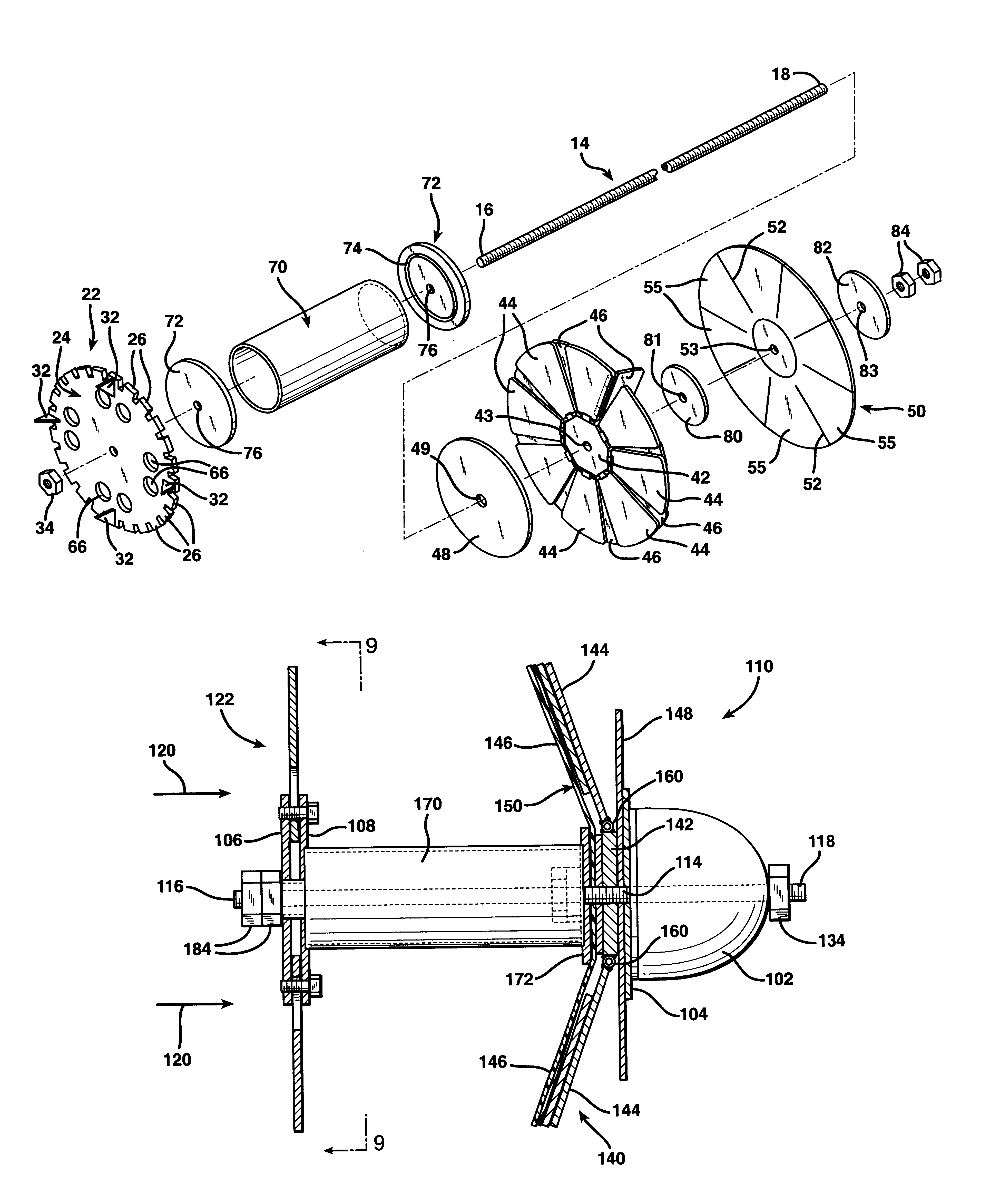
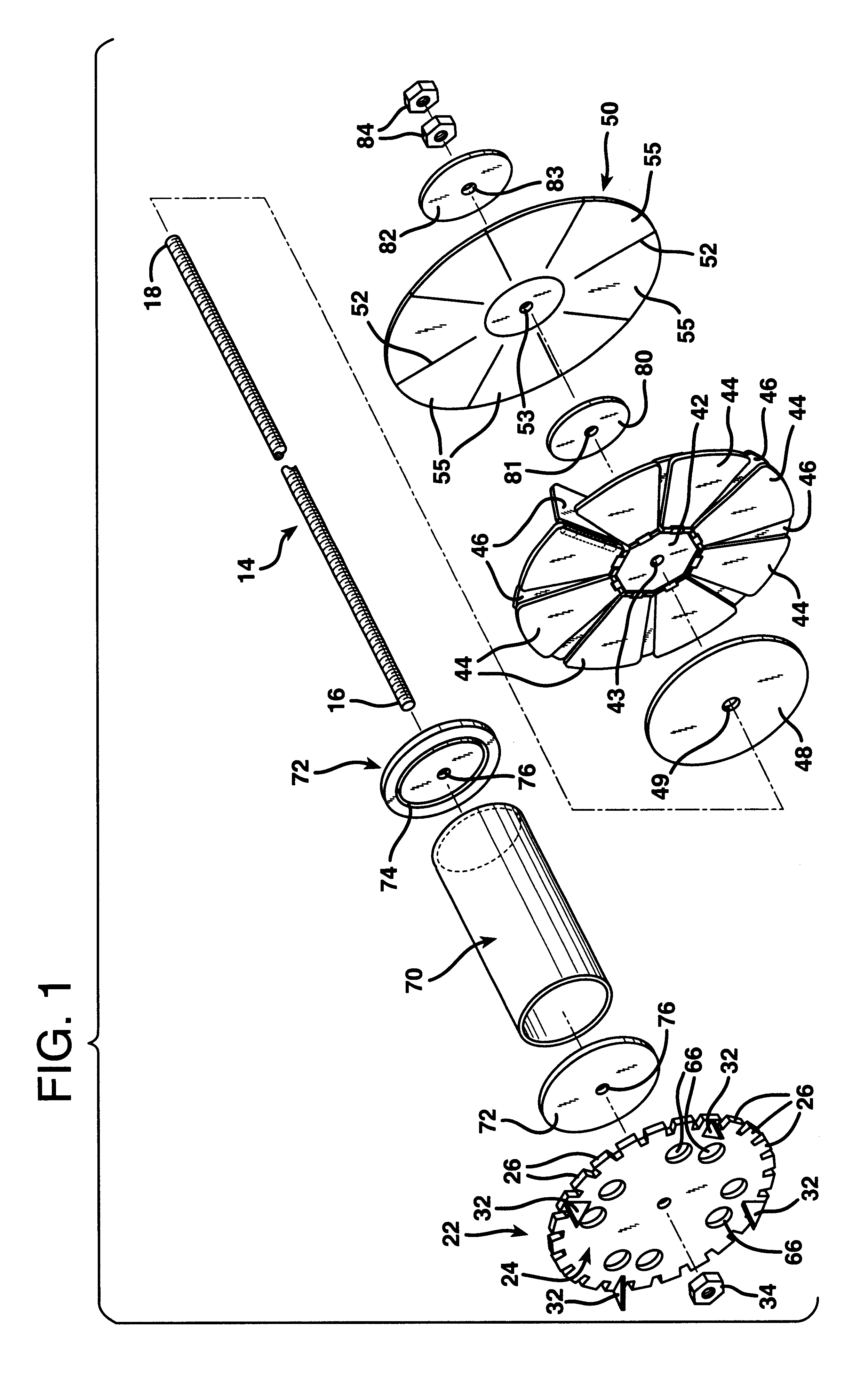
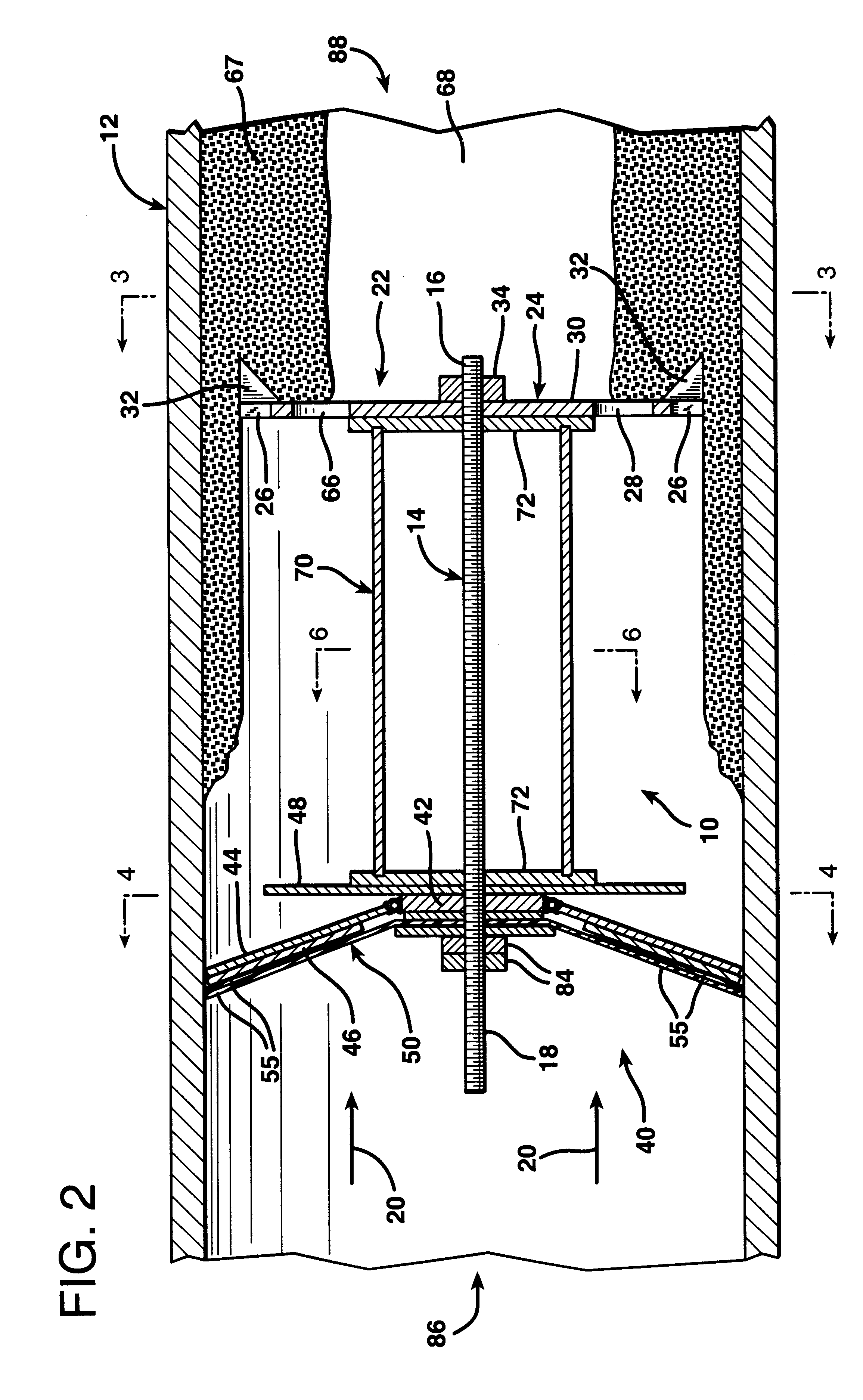
FIGS. 1 and 2 illustrate a pipeline cleaning tool 10 which may, for example, be constructed in a size suitable for cleaning a section of pipeline 12 having an inner diameter of twenty inches in a single pass through the section of pipeline 12. The pipeline cleaning tool 10 is formed with an elongated, central shaft 14 which is a one and one-quarter inch diameter externally threaded steel B7 stud. The length of the shaft 14 is governed by the radius of bends which the pipeline 12 makes. It is desirable for the central shaft 14 to be as long as possible so as to maintain the cleaning tool 10 in longitudinal alignment within the pipeline 12. However, the pipeline cleaning tool 10 must be short enough so that it is capable of traveling through bends in the pipeline 12. In the geothermal industry, bends in pipelines 12 typically have a standard radius which is equal to one and a half times the interior pipe diameter. Therefore, for a twenty inch pipe the maximum length of the central sha...


PUM


Abstract

A pipeline cleaning tool is constructed with an elongated support mechanism having a rigid cutting unit mounted at one end and a folding propulsion assembly mounted at the other end. The propulsion assembly includes a system of folding sector panels that are hinged to a central hub for rotation relative thereto about tangential axes of rotation. A separate expansion flap is secured to each sector panel for rotation relative thereto about a radially oriented axis of rotation by a hinged connection to one radial side edge. Each expansion flap partially overlaps the upstream face of the sector panel immediately adjacent to that upon which it is mounted. The area of overlap is controlled by the extent to which the sector panels of the propulsion unit are folded back toward the supporting shaft. The greater the extent of folding, the greater will be the area of overlap of each expansion flap upon the upstream face of an adjacent sector panel. A disc-shaped backing seal is employed immediately adjacent the sector panels and the expansion flaps against the upstream faces thereof. A pressure differential is thereby formed across the propulsion unit which propels the cleaning tool along a section of pipeline to be cleaned. Radially projecting teeth and, in some cases, longitudinally projecting blades, slice through and break up accumulated clogging material that adheres to the inside of the pipeline wall as the pipeline cleaning unit is forced through the pipeline by pressure against the upstream side of the propulsion unit. The distance of radial projection of the teeth of the cutting unit may be made adjustable.

Description

1. Field of the InventionThe present invention relates to a tool and method for cleaning deposits, scale and other buildup on the inside surfaces of pipelines.2. Description of the Prior ArtPetroleum, geothermal, sewage, and other pipelines utilized to conduct fluids often develop buildups of deposits, scale, and other materials on the inner wall surfaces of the pipes that make up the pipeline. Continued buildup of accretions on the walls of a pipeline reduces the volume of fluid that flows through the pipeline and increases the resistance to flow through the line. Eventually the opening through the center of the pipeline decreases in cross-sectional area to such a degree that cleaning of the pipeline is imperative in order for it to continue to be useful for the conduction of fluids.In conventional practice, maintenance to unclog pipelines in which clogging deposits can be scoured by water alone may be performed by creating an opening in a pipeline and inserting a cleaning hose int...

Claims


Application Information

Patent Timeline
IPC IPC(8): B08B9/04B08B9/02B08B9/055
CPCB08B9/055
Inventor ROWE, WILLIAM H.
Owner TNG ENERGY SERVICES
Why Eureka
Try Eureka