Pressure welding apparatus and pressure welding method

a welding apparatus and pressure welding technology, applied in the direction of auxillary welding devices, soldering devices, unstripped conductor connection devices, etc., can solve the problems of unavoidable need to reduce the thickness of partition walls, and the leakage of electrical current through contacts 120 through cutouts

Inactive Publication Date: 2002-04-16
TYCO ELECTRONICS SERVICES GMBH +1
View PDF6 Cites 11 Cited by
  • Summary
  • Abstract
  • Description
  • Claims
  • Application Information

AI Technical Summary

Problems solved by technology

However, as the installation pitch of contacts 120 has become smaller (e.g., a pitch of 2.2 mm) with the increase in density seen in connectors in recent years, it has become unavoidably necessar

Method used


Image

  • Pressure welding apparatus and pressure welding method
  • Pressure welding apparatus and pressure welding method
  • Pressure welding apparatus and pressure welding method

Examples


Embodiment Construction

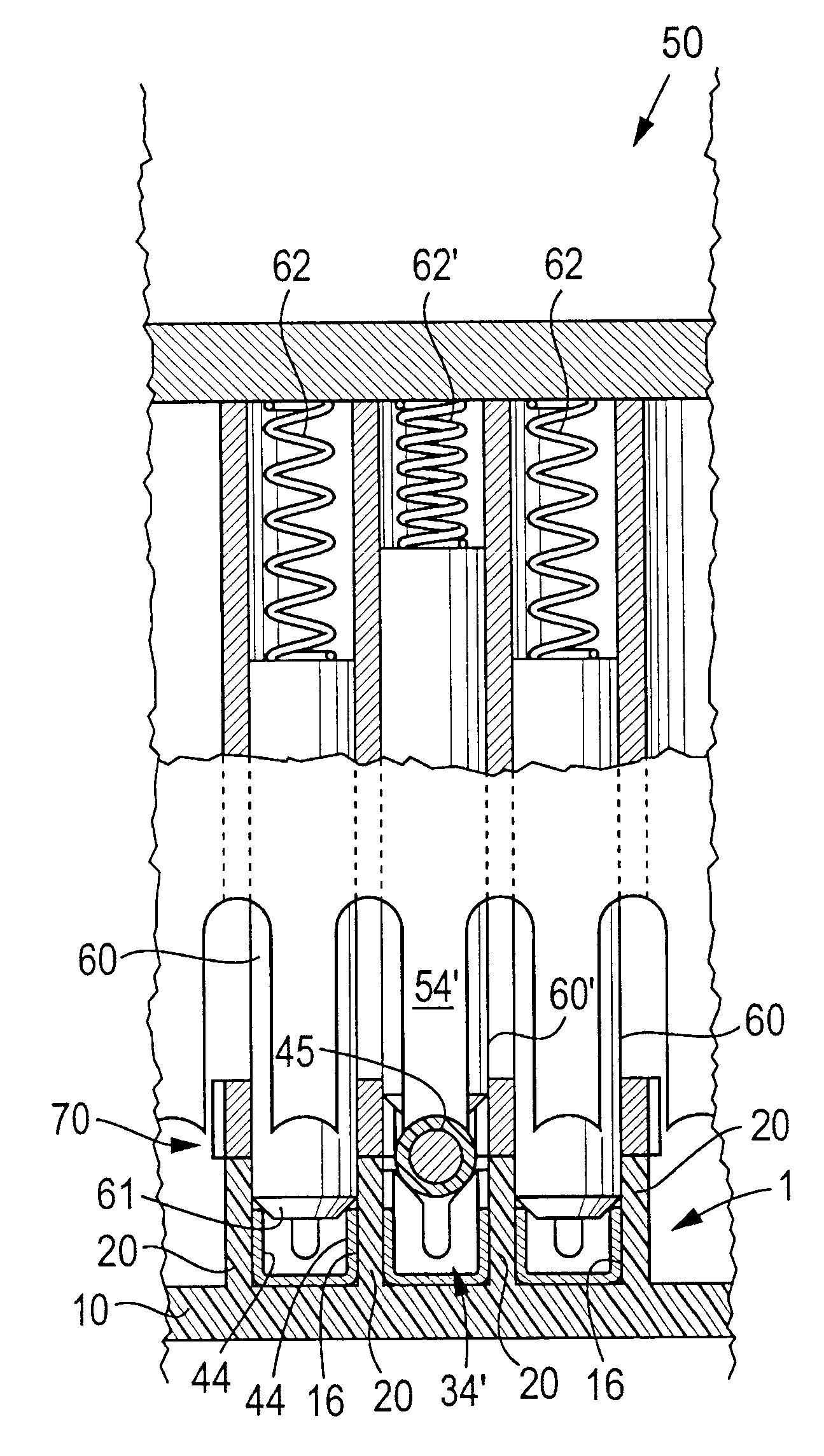
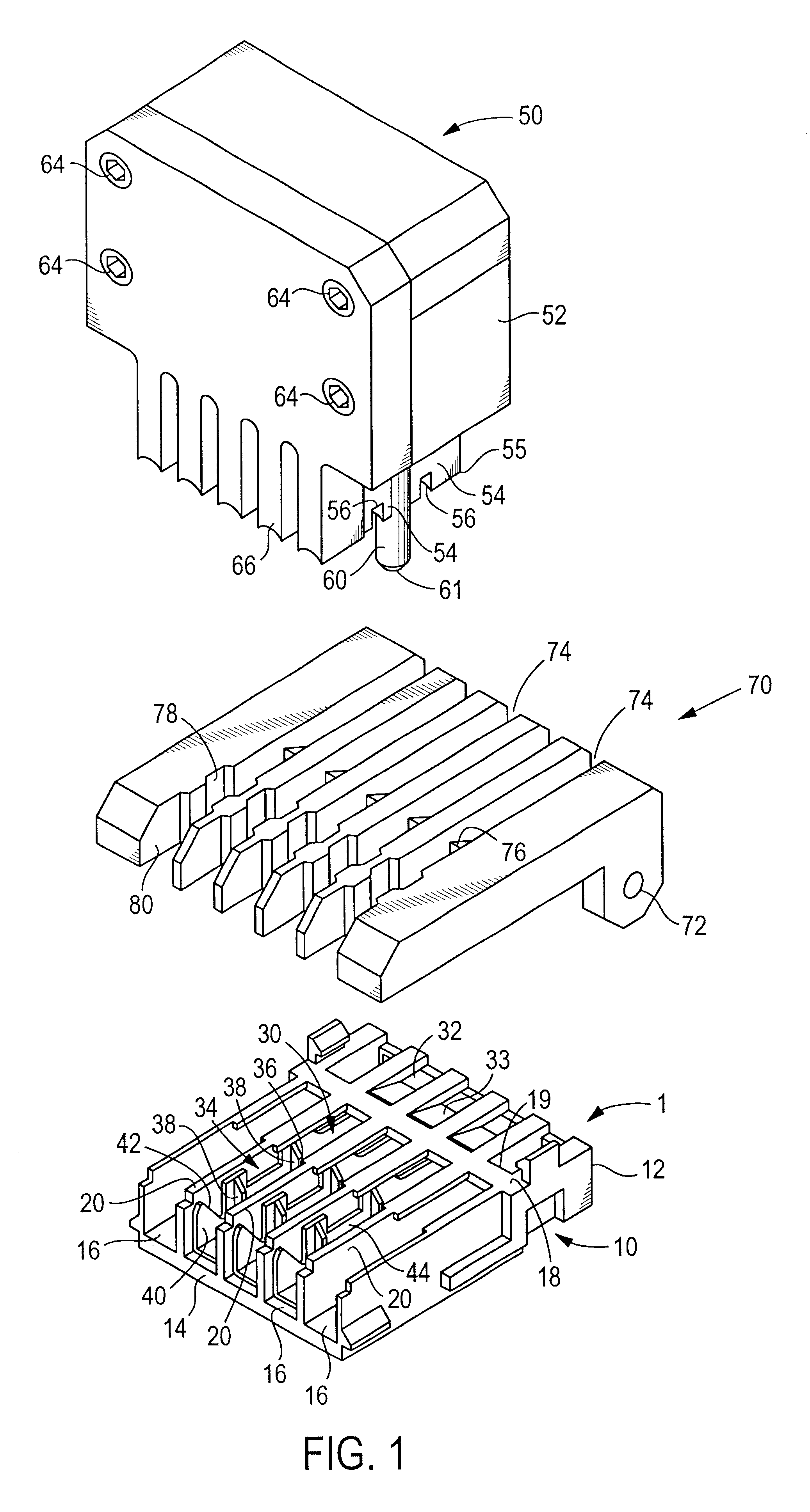
With reference to FIG. 1, a pressure-welding connector 1 comprises an insulating housing 10 and a plurality of pressure-welding contacts 30. The insulating housing 10, which is formed by injection-molding an appropriate plastic material, has a plurality of cavities 16 that communicate between front surface 12 and rear surface 14 of the housing 10. Within each cavity 16 is a contact 30 having a contact part 32. The housing 10 has an upper wall 18 which is disposed near the front surface 12 and which covers a portion of the contact parts 32 in the respective cavities 16. Partition walls 20 are disposed on both sides of each cavity 16. The height of the partition walls 20 is selected to be higher than the highest parts of the contacts 30. As a result, leakage of electrical current between adjacent contacts 30 is prevented.

Each of the pressure-welding contacts 30 is formed by stamping and bending a conductive metal plate. Each of the contacts 30 has a substantially box-shaped contact pa...


PUM

PropertyMeasurementUnit
Shapeaaaaaaaaaa
Widthaaaaaaaaaa

Abstract

A pressure welding apparatus includes a pressing die assembly 50 which has a plurality of stuffers 54 that pressure-weld electric wires 45 to the pressure-welding parts 34 of contacts 30, and a comb 70. The pressing die assembly 50 has a plurality of pins 60 which are located adjacent to the respective stuffers 54 and which are constantly driven downward by springs 62 so that the pins 60 protrude beyond the lower ends of the stuffers 54. The widths of the respective pins 60 are set so that these widths are substantially equal to the widths of the cavities 16 of the housing 10 in which the contacts 30 are accommodated. As a result, the pins 60 advance into the housing cavities 16 located adjacent to the contact 30 on which pressure-welding is to be performed, and support the housing partition walls 20 from the sides during the pressure welding process.

Description

The invention relates to a pressure welding apparatus and pressure welding method for pressure-welding electric wires to the pressure-welding parts of pressure-welding contacts.PRIOR ARTSoldering, press-bonding and pressure welding, etc., have been used in the past as methods for connecting electric wires to contacts. Among these methods, pressure welding is advantageous from the standpoint of the productivity of the connecting work. Pressure welding is spreading even in the Japanese automobile industry, in which pressure welding has not been very widely used in the past. The examples shown in FIGS. 8 through 11 are universally known as examples of a pressure-welding connector for use in automobiles and a pressure welding apparatus for use with this connector (Japanese Patent Application Kokai No. 10-326633).In FIG. 8, the pressure-welding connector 100 comprises a plurality of contacts 120, each of which has a contact part (not shown in the figures) and a pressure-welding part 122,...

Claims


Application Information

Patent Timeline
IPC IPC(8): H01R43/01
CPCH01R43/01
Inventor IKEDA, YUJIIMAI, KOJIISOHATA, SHIGERUAMEMIYA, SHINJI
Owner TYCO ELECTRONICS SERVICES GMBH
Why Eureka
Try Eureka