Seat back frame structure of a vehicle seat

Inactive Publication Date: 2002-04-23
TACHI S CO LTD
View PDF4 Cites 57 Cited by
  • Summary
  • Abstract
  • Description
  • Claims
  • Application Information

AI Technical Summary

Problems solved by technology

Hitherto, such problem has been solved by increasing the thickness of the lateral plate frame sections (14A), but it raises such problem that those particular frame sections (14A) themselves weigh greater unexpectedly, resulting in an inevitable cost increase, an unfavorable factor in practical assembly of seat cushion frame.
But, to further amplify the reinforcement, one will be forced to consider increasin

Method used


Image

  • Seat back frame structure of a vehicle seat
  • Seat back frame structure of a vehicle seat
  • Seat back frame structure of a vehicle seat

Examples


Embodiment Construction

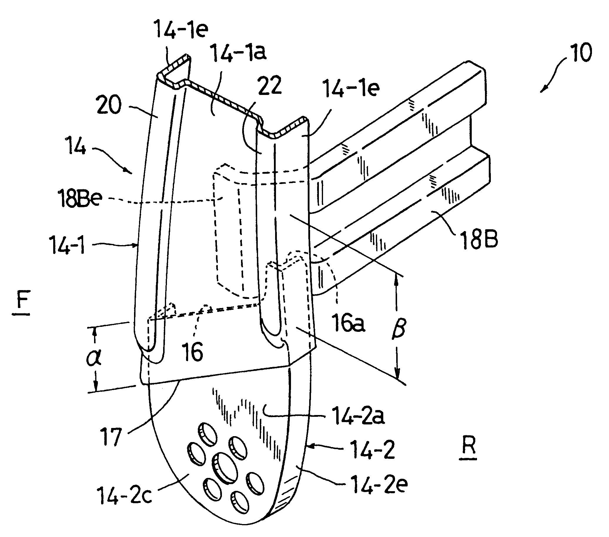
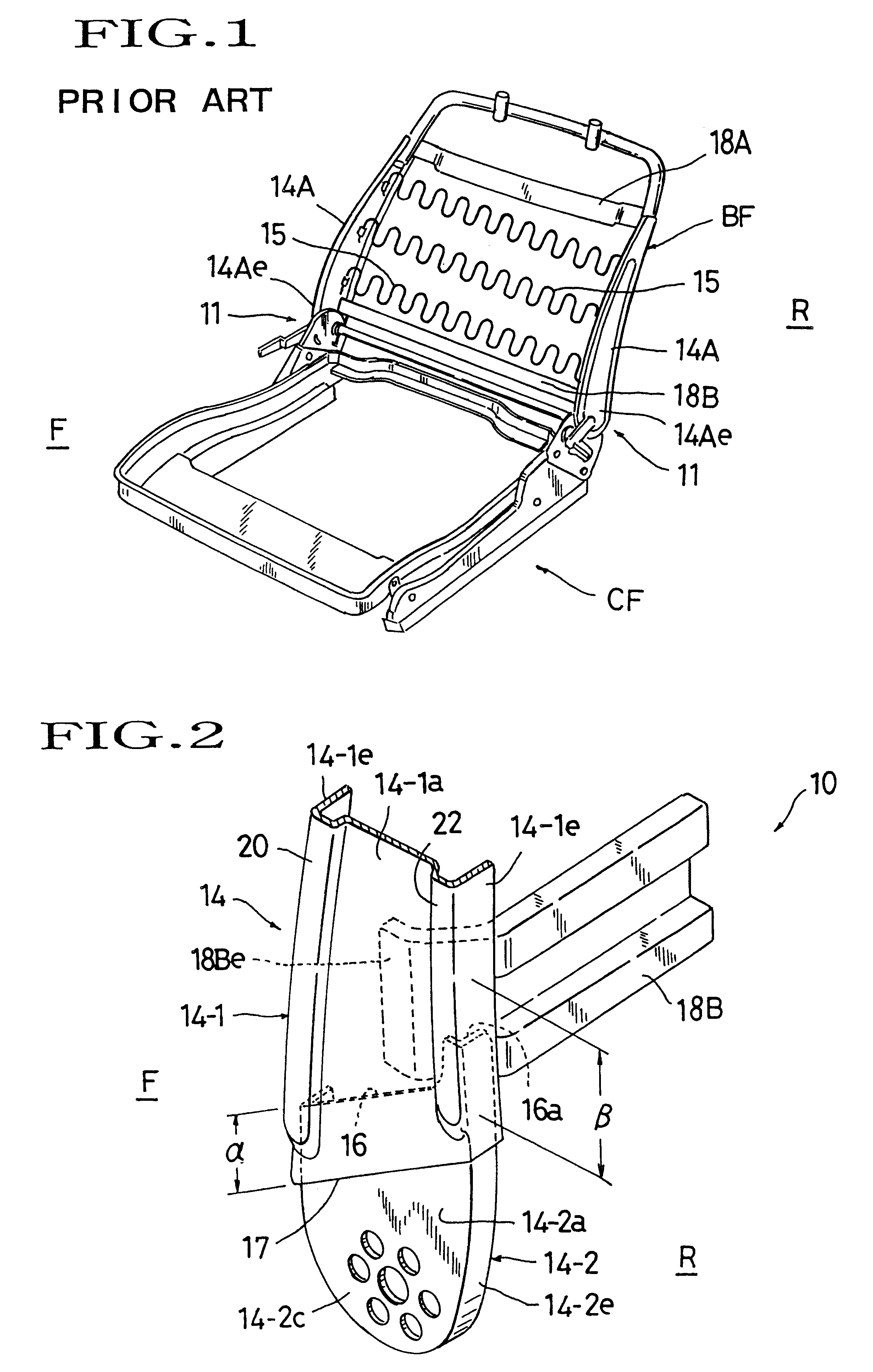
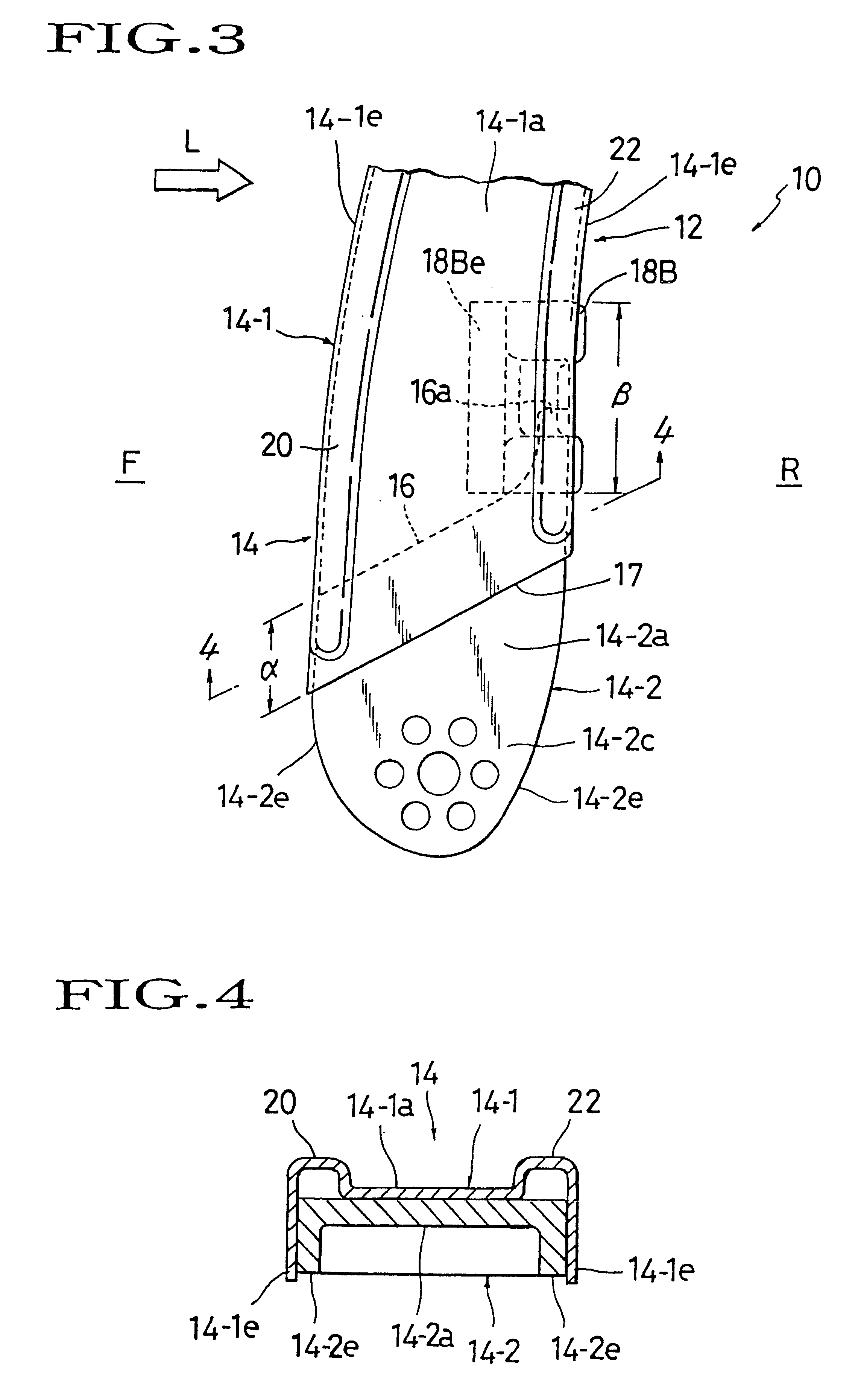
Referring to FIGS. 2 to 4, there is illustrated one exemplary mode of seat back frame structure in the present invention, as generally designated by (10). It should be first understood that this is an improvement based on the conventional structure of seat back frame (BF) which has been described earlier with reference to FIG. 1, and in particular concerned with the lower end portion (14Ae) of the lateral frame section (14A). Thus, the present invention utilizes such conventional seat back frame (BF) as shown in FIG. 1, and offers a novel improvement on the basis thereof, which will be described in detail. Any further specific description about the common parts and elements is therefore deleted for the sake of simplicity, and all like designations to be used hereinafter correspond to all like designations given in the preceding prior-art description and FIG. 1.

By way of a most preferred embodiment, as shown in FIGS. 2 and 3, the seat back frame structure (10) contemplated in the pre...


PUM


Abstract

A structure of seat back frame for use in a seat back of a vehicle seat, which includes a lateral frame section connected with upper and lower frame sections to comprise the seat back frame. The lower end portion of such seat-back lateral frame section has been cut to provide a reduced lower end area therein. On the other hand, a connecting bracket member is provided, which has an upper end portion with a slant edge and also has a large thickness relative to that of the lateral frame section. In the present structure, the connecting bracket member is fixedly connected, at that upper end portion thereof, to the reduced lower end area of lateral frame section, in such a manner that the slant edge thereof extends in a downwardly inclined way as it proceeds toward a forward side of the seat back, i.e. a running direction of a vehicle.

Description

BACKGROUND OF INVENTION1. Field of the InventionThe present invention relates to a seat back framework of a vehicle or automotive seat, and in particular to a structure of seat back frame which includes a lateral frame section and a connecting bracket fixed to the lower end portion of that lateral frame section, wherein the connecting bracket is adapted for operative connection, via a reclining device or the like, with the side of a seat cushion frame.2. Description of Prior ArtAs shown, for instance, in FIG. 1, most of conventional seat back frameworks, designated by (BF), are generally of a rectangular configuration on the whole. Some of the seat back frameworks of this sort, as in the FIG. 1, comprise an upper frame section (18A), a lower frame section (18B) and a pair of lateral plate frame sections (14A) (14A) fixedly connected between the upper and lower frame sections (18A) (18B). A plurality of springs (15) are extended between the two lateral plate frame sections (14A) for ...

Claims


Application Information

Patent Timeline
IPC IPC(8): B60N2/68B60N2/42A47C7/40
CPCB60N2/68B60N2/22
Inventor ISHIKAWA, TAKESHI
Owner TACHI S CO LTD
Why Eureka
Try Eureka