Pipe coupling

a technology of pipe coupling and sleeve, which is applied in the direction of hose connection, sleeve/socket joint, fluid pressure sealing joint, etc., and can solve problems such as difficult operation

Inactive Publication Date: 2002-04-30
PLASSON LTD
View PDF3 Cites 61 Cited by
  • Summary
  • Abstract
  • Description
  • Claims
  • Application Information

AI Technical Summary

Problems solved by technology

However, for pipes of large diameters, the operation of pushing the pipe through the O-ring seal requires a large force, making the operation very difficult, and sometimes even necessitating an extra operation of chamfering the pipe end for this purpose.
A further disadvantage in pipe couplings of the type herein described now in use is that such couplings do not tolerate substantial variations in the pipe diameter so that precise pipe diameter tolerances must be maintained, or a large number of differences in diameter sizes; improved sealing even or damaged pipes, particularly since the seal produces double sealing points; and convenient disassembly of the coupling, since relaxation of the sealing ring releases the pipe end for removal and also "springs" the compression sleeve, the split ring and the nut during disassembly.

Method used


Image

  • Pipe coupling
  • Pipe coupling
  • Pipe coupling

Examples


Embodiment Construction

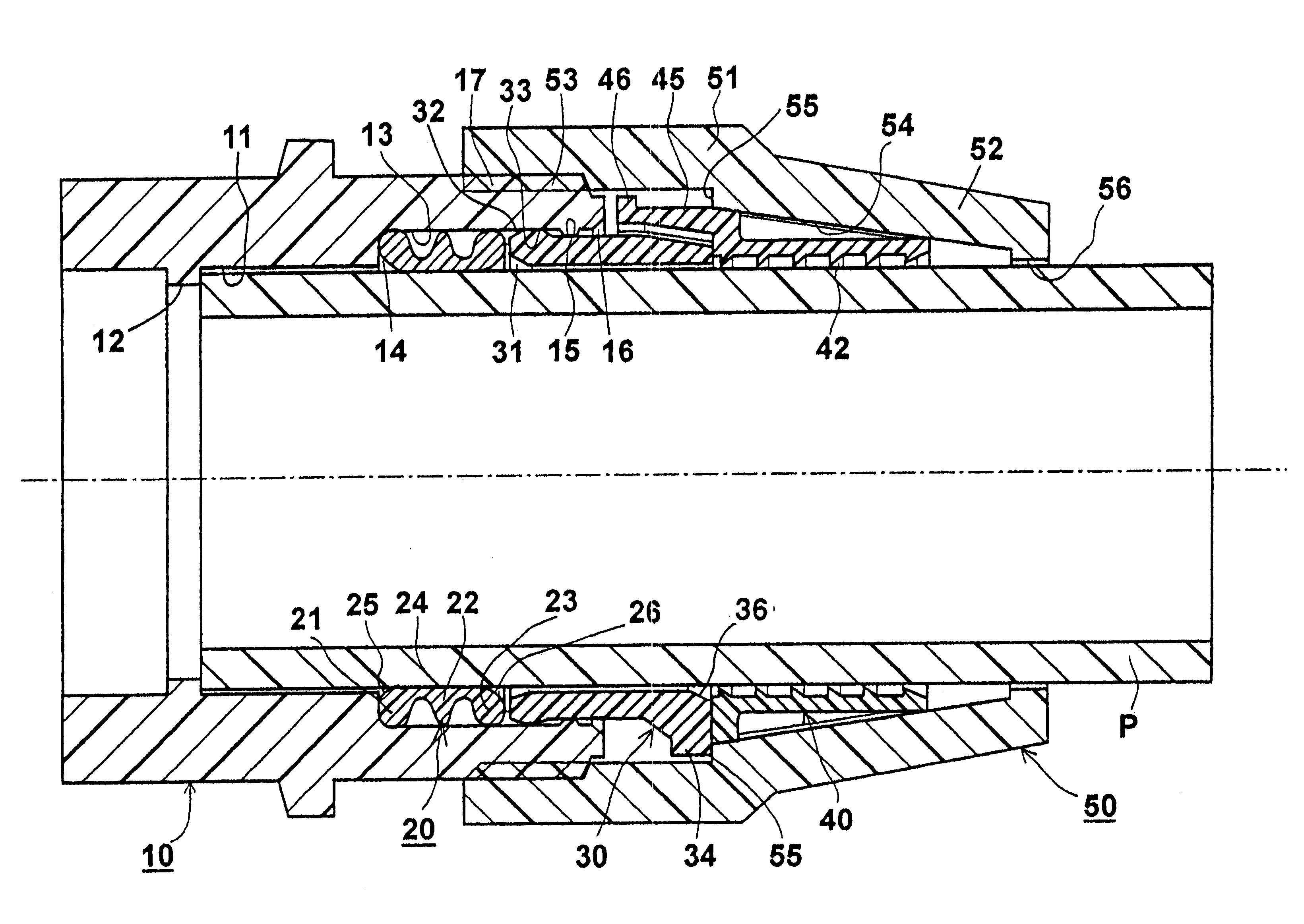
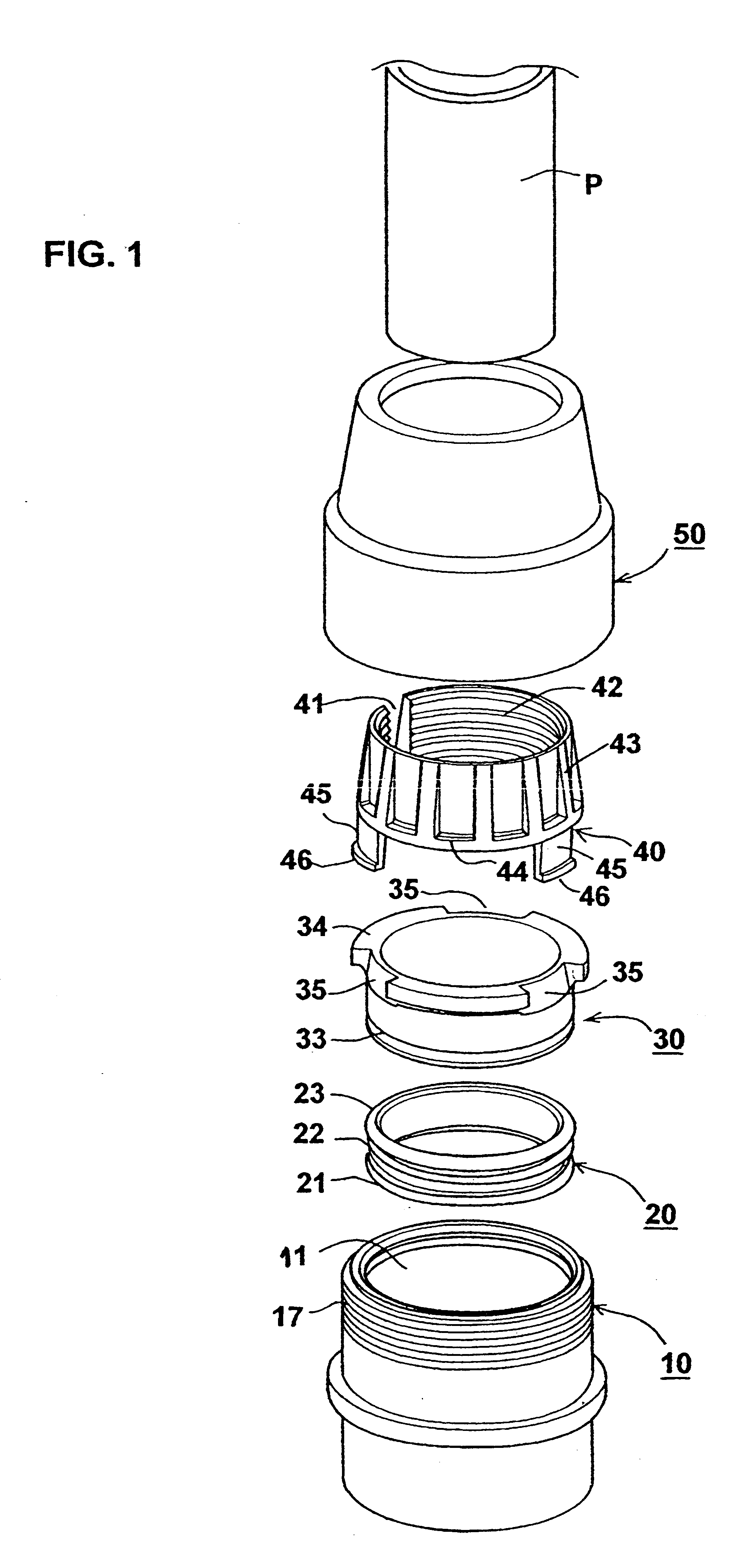
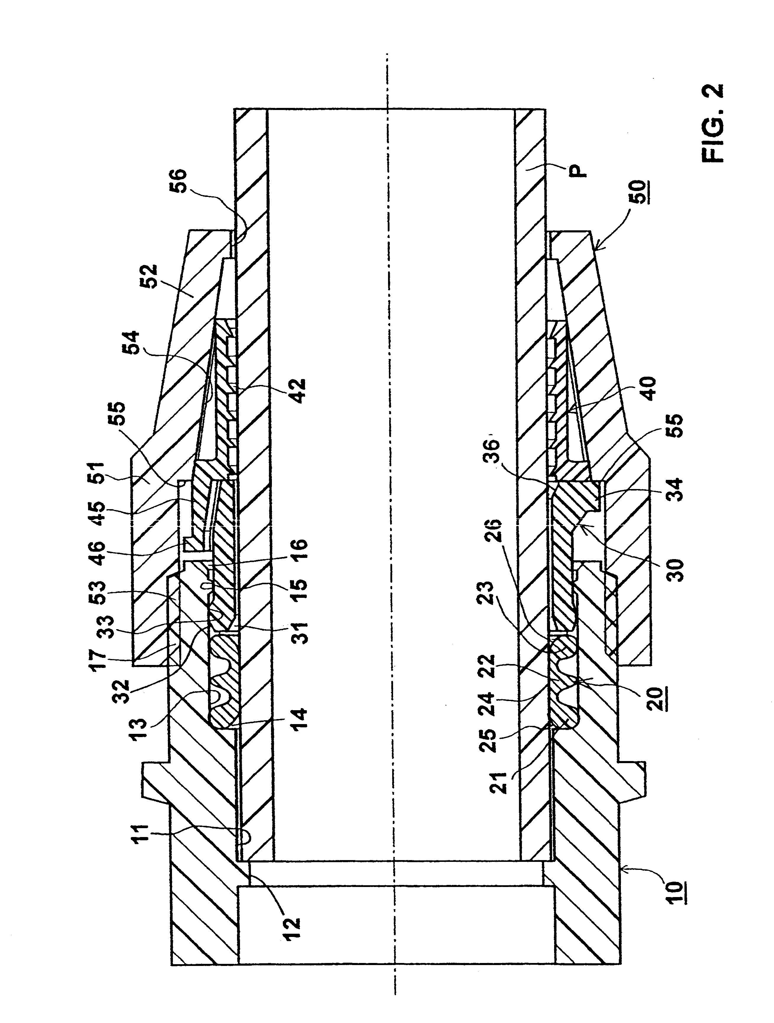
The Embodiment of FIGS. 1-3

The pipe coupling illustrated in FIGS. 1-3 is of the type herein described (as defined above) but modified to include the features of the present invention set forth above, and as to be described more particularly below. As shown in FIG. 1, such a pipe coupling includes the following basic parts: a body member 10; a sealing ring 20; addition, its outer surface is formed with a shallow annular rib 33 at the end of the sleeve facing body member 10. Rib 33 is cooperable with rib 15 of the body member to releasably hold the compression sleeve, and with it the resilient ring 20, during the assembling of the coupling.

The opposite end of the compression sleeve 30, i.e., the end facing the gripping ring 40, is formed with a radial flange 34 having a plurality (in this case three) axially-extending slots or recesses 35 spaced around its periphery, for reasons to be described below. The inner surface of flange 34 facing the gripping ring 40 is inwardly tapered in th...


PUM


Abstract

A pipe coupling includes a body member (10) formed with a bore (11) for receiving one end of a pipe (P) to be coupled; a sealing ring (20) and a compression sleeve (30) receivable within the bore (11); a radially-deformable gripping ring (40) having one end abuttable against the compression sleeve (30), a securing nut (50) threaded on the body member (10) and engageable with the gripping ring (40) to move the gripping ring (40) axially and to effect a sealing action via the compression sleeve (30) and the sealing ring (20), and also to compress the gripping ring (40) radially to effect a gripping action of the pipe (P) received in the bore (11); and an axially-extending limit element (45) between the gripping ring (40) and the body member (10) effective to cause the nut (50), when tightened; (a) in an initial stage, to move the gripping ring (40) and the compression sleeve (30) until the limit element engages (45) prevents further axial movement of the gripping ring (40); and (b) in a final stage, to radially deform the gripping ring (40) to produce the gripping action, and then to compress the sealing ring (20) against the internal annular shoulder (14) of the body member to produce the sealing action.

Description

FIELD AND BACKGROUND OF THE INVENTIONThe present invention relates to pipe couplings, and particularly to pipe couplings of the compression type, such as are described, for example in U.S. Pat. Nos. 4,025,093 and 4,083,587, assigned to the assignee of the present application.Pipe couplings of this type generally comprise: a body member formed with a bore for receiving one end of a pipe to be coupled, an annular shoulder to enclose the pipe when received in the bore, and threads for threadedly receiving a securing nut; a sealing ring receivable within the bore and engageable with the annular shoulder for producing a sealing action with respect to the pipe when received in the bore; a compression sleeve also receivable within the bore and engageable with the sealing ring for compressing the sealing ring against the annular shoulder of the body member; a radially-deformable gripping ring having one end abuttable against the compression sleeve, and also having an inner surface producing...

Claims


Application Information

Patent Timeline
Patent Type & Authority Patents(United States)
IPC IPC(8): F16L19/00F16L19/08
CPCF16L19/086F16L33/00
Inventor KATZ, ODED
Owner PLASSON LTD
Why Eureka
Try Eureka