Wheel with a generator

Inactive Publication Date: 2002-05-28
LIU MENG YU
View PDF4 Cites 34 Cited by
  • Summary
  • Abstract
  • Description
  • Claims
  • Application Information

AI Technical Summary

Problems solved by technology

The fun of using the r

Method used


Image

  • Wheel with a generator
  • Wheel with a generator
  • Wheel with a generator

Examples


Embodiment Construction

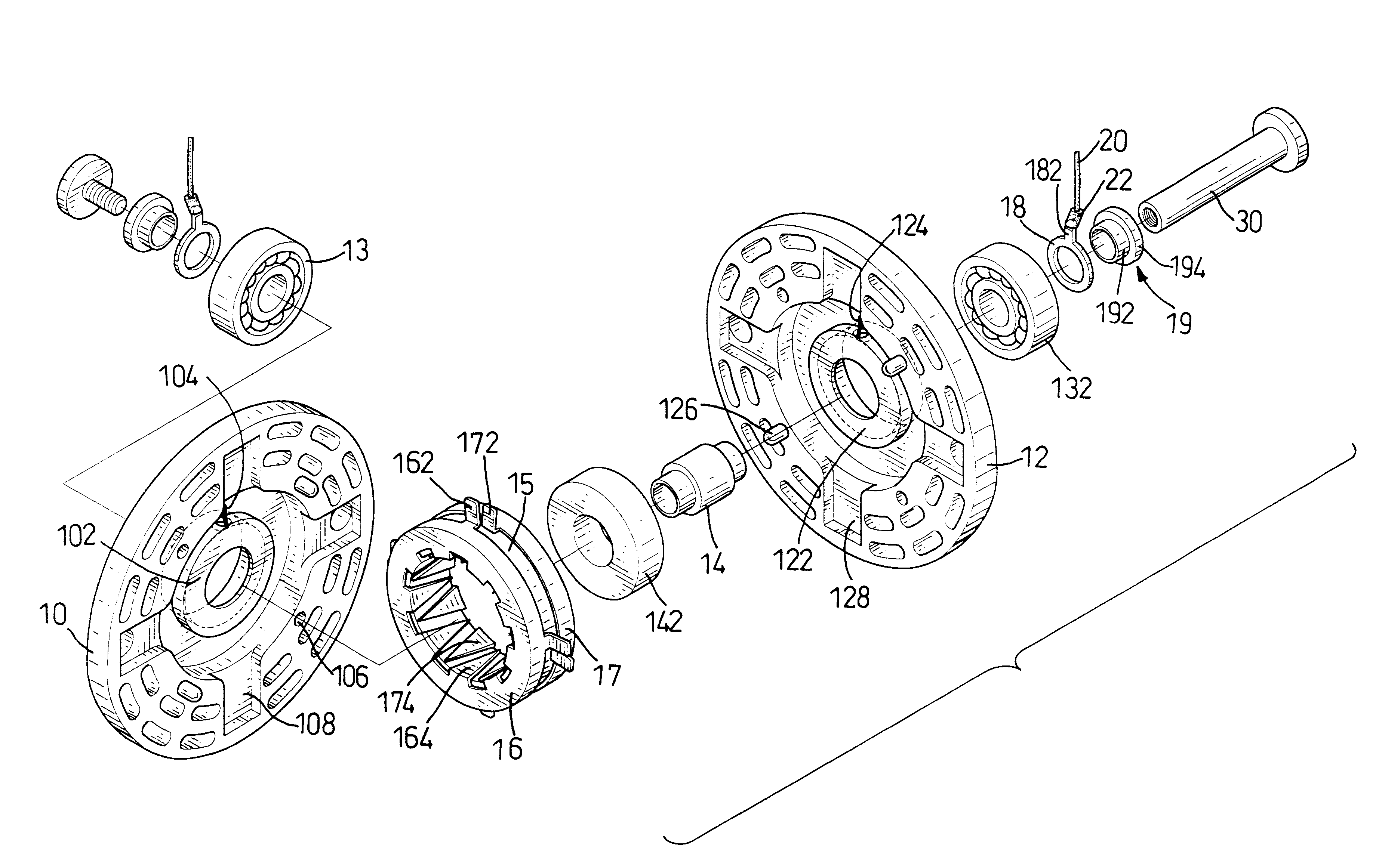
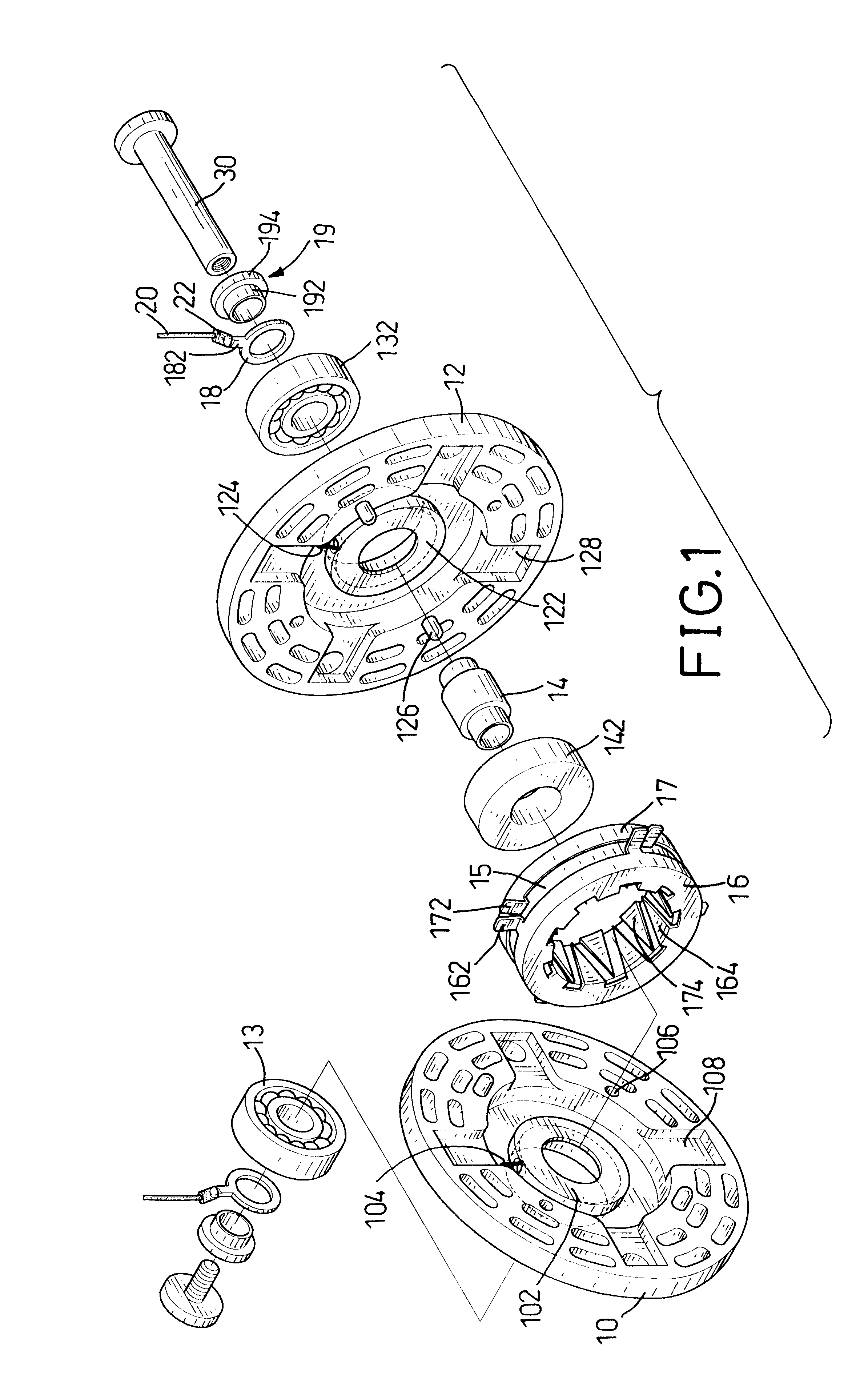
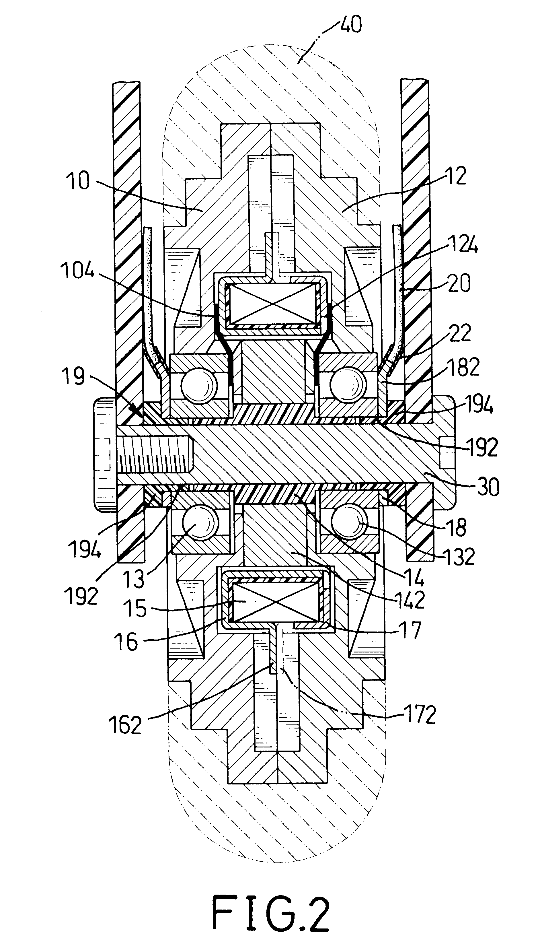
With reference to FIGS. 1 and 2, a wheel for in accordance with the present invention comprises two wheel halves (10, 12), a generator, two bearings (13,132) and two metal rings (18). The wheel is mounted on a roller skate, a skateboard or the like. Both of the bodies (10, 12) are circular. One of the wheel halves (10) has multiple holes (106) defined in the body (10). The other wheel half (12) has Stubs (126) corresponding to the holes (106) extending from the wheel half (12) and engaging the corresponding holes (106) in the opposite wheel half (10). Consequently, the wheel halves (10, 12) are securely connected to each other by the engagements between the holes (106) and the stubs (126) such that they rotate as a single element. A tire (40) is mounted around the wheel halves (10, 12) to enclose the outer peripheries of the wheel halves (10, 12). Accordingly, the wheel halves (10, 12) will not unintentionally disengage from each other because the tire (40) securely holds the wheel ...


PUM


Abstract

A wheel has two wheel halves, a generator, two bearings and two metal rings. The wheel halves are detachably connected to each other. The generator is composed of an annular coil seat and an annular permanent magnet. The coil seat is securely mounted between the wheel halves and has a winding wound around the coil seat. The permanent magnet is rotatably mounted between the wheel halves. Each bearing is received in one of the wheel halves and electrically connects with one end of the winding. Each ring is securely attached to one of the wheel halves to abut the bearing. Consequently, the coil seat will rotate with the wheel bodies and relative to the permanent magnet and generate electricity. The electricity will be transmitted to a lighting device or a sounding device. The enjoyment of a roller skate or a skateboard with the wheel is improved.

Description

1. Field of the InventionThe present invention relates to a wheel, and more particularly to a wheel with a generator for a roller skate or a skateboard.2. Description of Related ArtWith reference to FIG. 4, a conventional roller skate comprises a frame (60), multiple wheels (62) and a shoe (64). The wheels (62) are rotatably mounted on the bottom of the frame (60) and arranged in a row. The shoe (64) is attached to the top of the frame (64) for a person to wear. The conventional wheel (62) for a roller skate is made of plastic or the like. The conventional wheel (62) cannot provide sound or light to the roller skate. The fun of using the roller skate is limited.To overcome the shortcomings, the present invention tends to provide a wheel with a generator to mitigate or obviate the aforementioned problems.The main objective of the invention is to provide a wheel with a generator to generate electricity when the wheel rotates. The wheel has two halves, a generator, two bearings and two...

Claims


Application Information

Patent Timeline
IPC IPC(8): H02K7/18
CPCH02K7/1846
Inventor CHIU, CHUN-CHEN
Owner LIU MENG YU
Why Eureka
Try Eureka