X-ray collimator

a collimator and x-ray technology, applied in the field of radiography, can solve the problems of reducing so as to achieve the effect of improving the efficiency of the collimator and reducing the radiation dos

Inactive Publication Date: 2002-05-28
ANLOGIC CORP (US)
View PDF12 Cites 127 Cited by
  • Summary
  • Abstract
  • Description
  • Claims
  • Application Information

AI Technical Summary

Benefits of technology

The present disclosure also provides an assembly for selecting one of the slits of the collimator. The assembly includes a selection motor having a rotatable shaft, and a gear mechanism coupling the motor shaft to the collimator for rotating the collimator about its rotation axis to select a slit. According to one aspect, a resilient material is seated in a circumferential groove of at least one gear of the gear mechanism for absorbing shock. According to another aspect, an index pin is provided for receipt in an index aperture of the gear mechanism for fine tuning and locking the rotated position of the collimator.

Problems solved by technology

The conventional collimator design is problematic, however, since the actual cross-sectional shape of the beam produced by the collimator is not precisely rectangular but is instead wider at its center than at its ends, i.e., convex.
In addition, the convex beam cross-section may subject a patient to a dose of x-rays in excess of those required for the scan.
A patient being scanned, therefore, may be subject to an unnecessary radiation dose since the portion of the beam cross-section extending beyond the detectors is unused.
Another problem associated with conventional computer tomography scanners arises due to component movement, or drifting, that occurs during operation of the scanners.
Consequently, any movement of the various tomography components during a scan can cause major inaccuracies in reconstructed images.
One particular cause of unwanted movement is the beam source itself.
For example, as the anode of the beam source heats up during operation, thermal expansion causes the focal spot to shift, thus causing the resulting x-ray beam to shift with respect to the collimator.
The focal spot shifting can detract from the integrity of the image data and can cause major inaccuracies in the reconstructed image.

Method used


Image

  • X-ray collimator
  • X-ray collimator
  • X-ray collimator

Examples


Embodiment Construction

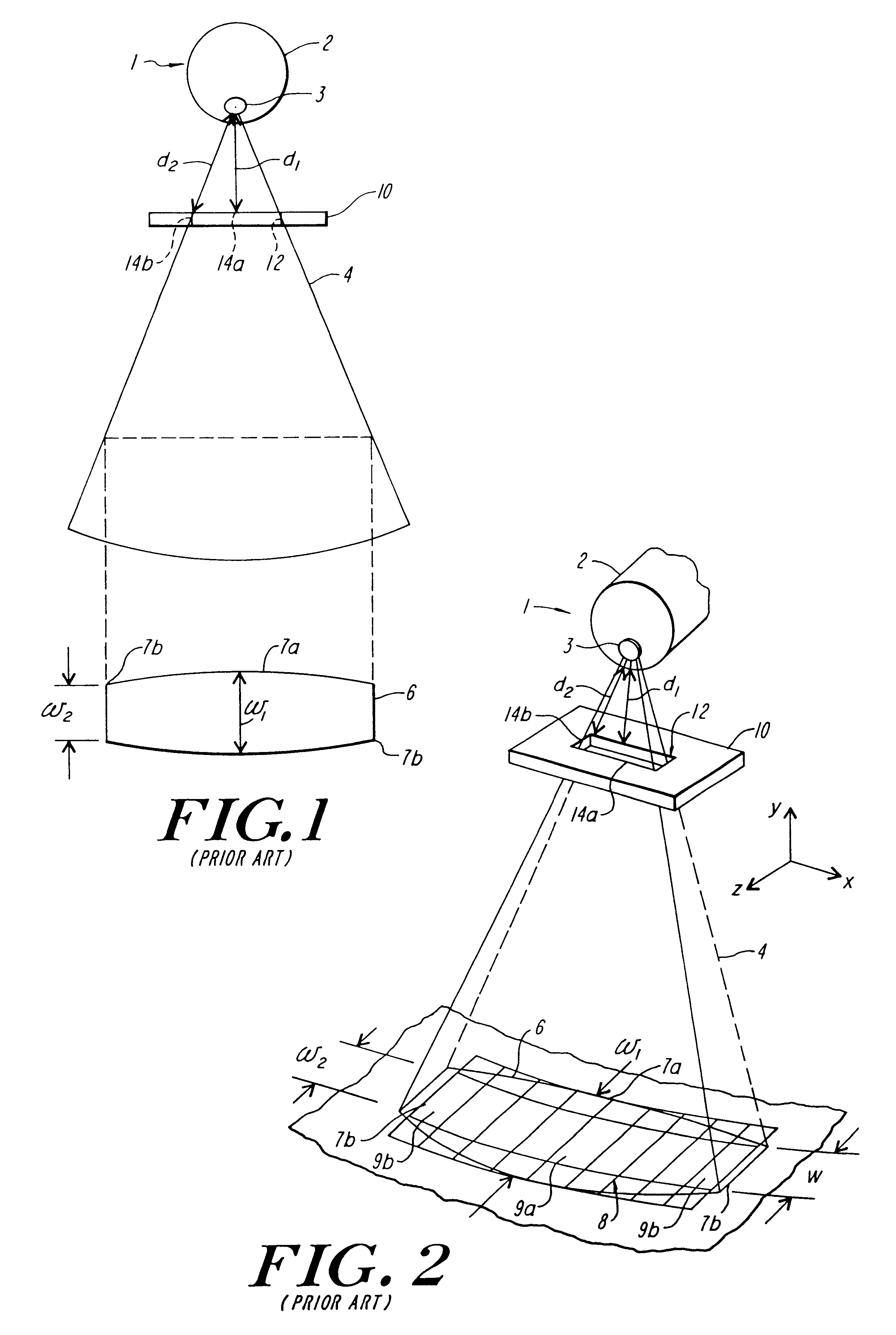
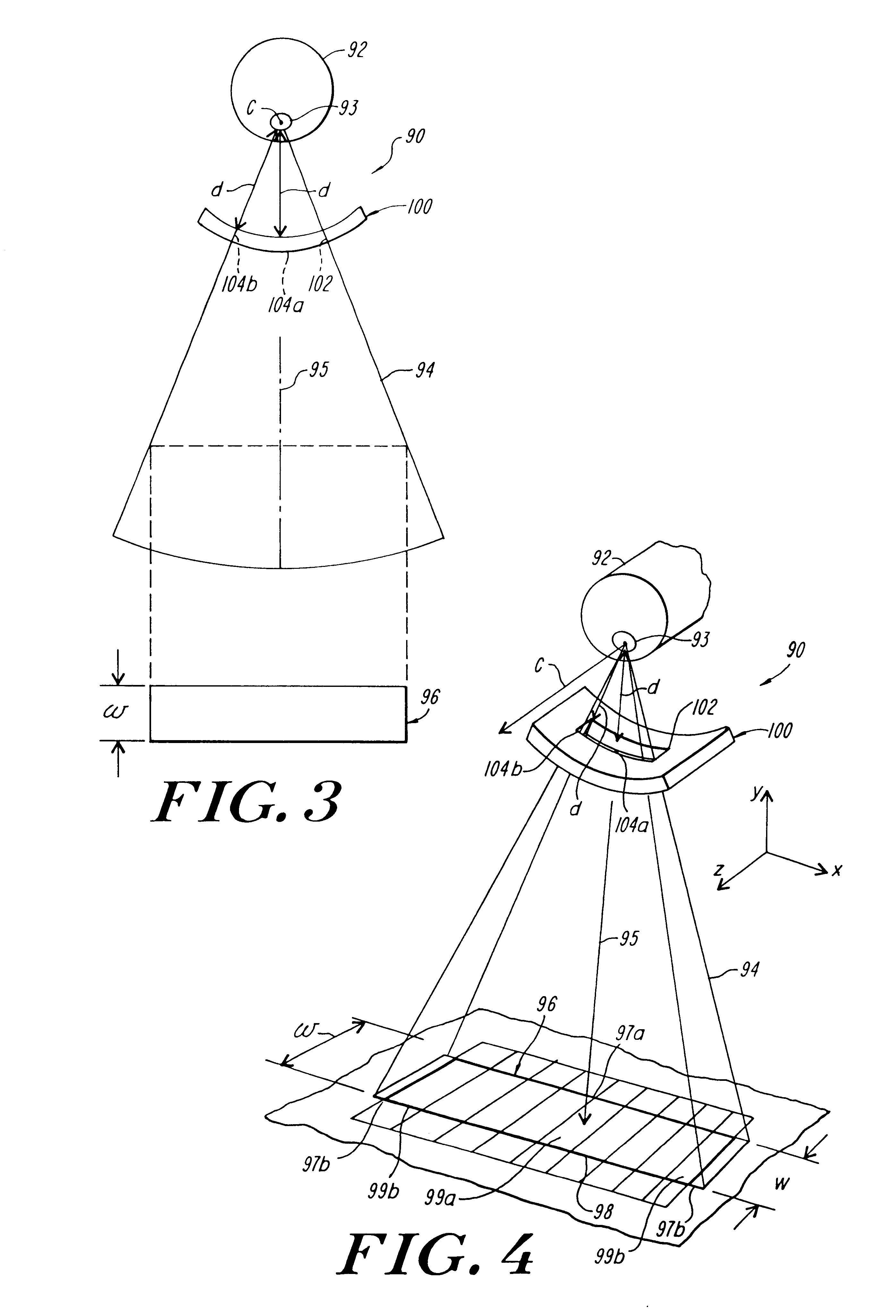
Referring first to FIGS. 3 and 4, in computed tomography, a patient (not shown) to be examined is positioned in a scan circle of a computer tomography scanner 90, parallel with a z-axis, and between an x-ray source 92 and a rectangular detector array 98. The x-ray source 92 then projects a beam of energy, or x-rays 94 from a focal spot 93, through the patient, to the detector array 98. By rotating the x-ray source 92 about the z-axis and relative to the patient, radiation is projected through a portion of the patient to the detector array 98 from a many different directions around the patient. An image of the scanned portion of the patient then is constructed from data provided by the detector array 98, which has a uniform width W.

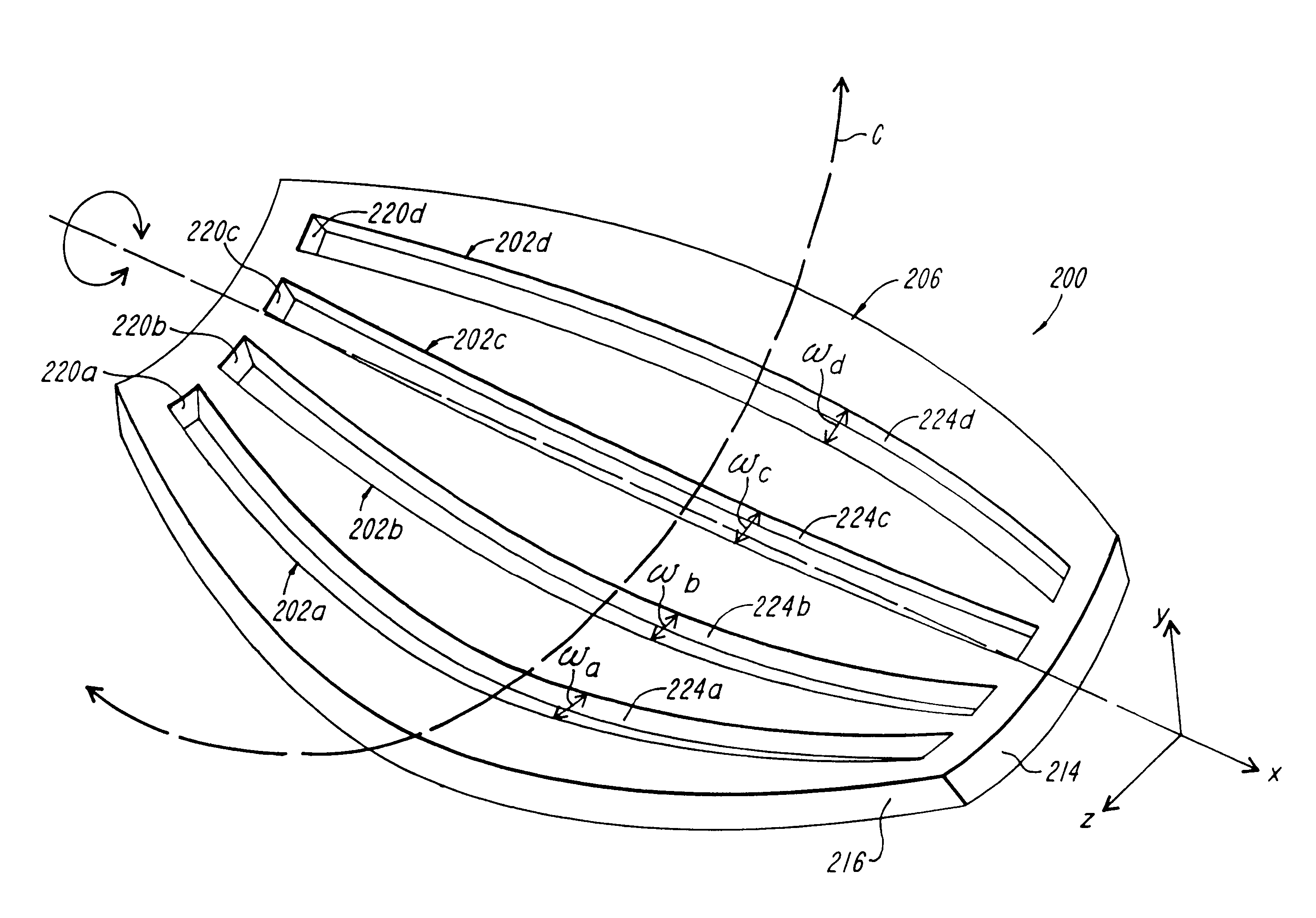
The scanner 90 of FIGS. 3 and 4 employs a collimator 100 constructed in accordance with the present disclosure. The collimator is shown in greater detail in FIGS. 5-7, wherein like reference characters refer to the same parts throughout the different views...


PUM


Abstract

A collimator having slits of varied widths, wherein each slit includes a curved side profile having a common axis of curvature for providing a cross-section of an emitted beam of energy with a substantially uniform width when the common axis of curvature of the slit intersects a focal spot of a source of the beam. The collimator is curved about a rotation axis substantially normal to the common axis of curvature, such that rotating the collimator about the rotation axis will sequentially position the slits to collimate the emitted beam.

Description

FIELD OF DISCLOSUREThe present disclosure relates to the field of radiography and, in particular, relates to computer tomography scanners. Even more particularly, the present disclosure relates to a collimator and a collimator assembly for use with a computer tomography scanner.BACKGROUND OF DISCLOSUREIn computed tomography, a patient to be examined is positioned in a scan circle of a computer tomography scanner. A shaped x-ray beam is then projected from an x-ray source through the scan circle and the patient, to an array of radiation detectors. By rotating the x-ray source and the collimator relative to the patient (about a z-axis of the scanner), radiation is projected through an imaged portion of the patient to the detectors from a multiplicity of directions. From data provided by the detectors, an image of the scanned portion of the patient is constructed.Within the x-ray source, an electron beam strikes a focal spot point or line on an anode, and x-rays are generated at the fo...

Claims


Application Information

Patent Timeline
Patent Type & Authority Patents(United States)
IPC IPC(8): G21K1/02
CPCG21K1/025
Inventor TYBINKOWSKI, ANDREW P.DUFFY, MICHAEL J.NEMIROVSKY, LIDIABAILEY, ERIC M.
Owner ANLOGIC CORP (US)
Why Eureka
Try Eureka