Cone-beam computerized tomography with a flat-panel imager

Inactive Publication Date: 2003-01-09
WILLIAM BEAUMONT HOSPITAL
View PDF2 Cites 254 Cited by
  • Summary
  • Abstract
  • Description
  • Claims
  • Application Information

AI Technical Summary

Problems solved by technology

Unfortunately, delivery of increased dose is limited by the presence of adjacent normal structures and the precision of beam delivery.
Furthermore, the location and orientation of the lesion can vary during a single treatment session (resulting in intrafraction errors) due to normal biological processes, such as breathing, peristalsis, etc.
Applying large margins necessarily increases the volume of normal tissue that is irradiated, thereby limiting the maximum dose that can be delivered to the lesion without resulting in complication in normal structures.
However, it is often the case that the maximum dose that can be safely delivered to the target volume is limited by the associated dose to surrounding normal structures incurred through the use of margins.
This obvious shortcoming can be alleviated by implanting radio-opaque mar

Method used


Image

  • Cone-beam computerized tomography with a flat-panel imager
  • Cone-beam computerized tomography with a flat-panel imager
  • Cone-beam computerized tomography with a flat-panel imager

Examples


Embodiment Construction

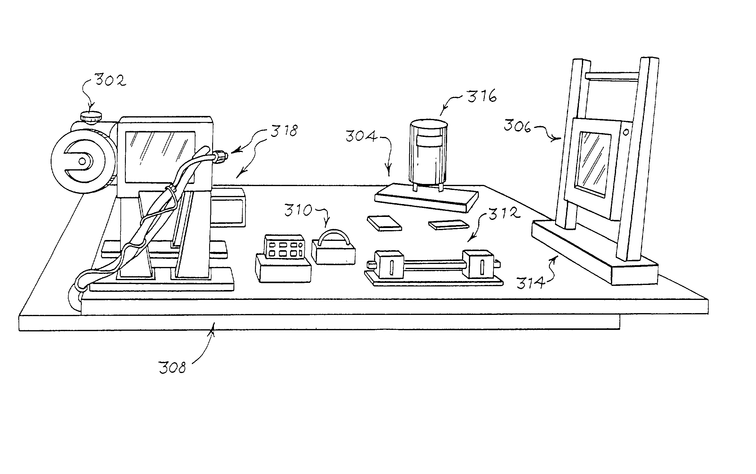
[0053] A bench-top cone beam computerized tomography (CBCT) system 300 is shown in FIG. 3, according to an embodiment of the present invention. The CBCT system 300 was constructed to mimic the geometry of the CBCT scanner currently installed on a linear accelerator, with a source-to-axis distance of 1000 mm and a source-detector distance of 1600 mm. The primary components of the system 300 include an x-ray tube 302, a rotation stage 304 and flat-panel imager (FPI) 306. These components are rigidly mounted to an optical bench 308. The relative position of these components is controlled by three translation stages, including an object stage 310, a yobject stage 312 and a yimage stage 314, which are used during initial setup to accurately determine and control the imaging geometry. The cone beam computerized tomography system 300 generates images of an object 316, identified throughout as a phantom, mounted on the rotation stage 304. Each stage 310, 312 and 314 contains a home or limit...


PUM


Abstract

A radiation therapy system that includes a radiation source that moves about a path and directs a beam of radiation towards an object and a cone-beam computer tomography system. The cone-beam computer tomography system includes an x-ray source that emits an x-ray beam in a cone-beam form towards an object to be imaged and an amorphous silicon flat-panel imager receiving x-rays after they pass through the object, the imager providing an image of the object. A computer is connected to the radiation source and the cone beam computerized tomography system, wherein the computer receives the image of the object and based on the image sends a signal to the radiation source that controls the path of the radiation source.

Description

[0001] Applicants claim, under 35 U.S.C. .sctn.119(e), the benefit of priority of the filing date of Feb. 18, 2000, of U.S. Provisional Patent Application Serial No. 60 / 183,590, filed on the aforementioned date, the entire contents of which are incorporated herein by reference.[0002] 1. Field of the Invention[0003] The present invention relates generally to a cone-beam computed tomography system and, more particularly, to a cone-beam computed tomography system that employs an amorphous silicon flat-panel imager for use in radiotherapy applications where the images of the patient are acquired with the patient in the treatment position on the treatment table.[0004] 2. Discussion of the Related Art[0005] Radiotherapy involves delivering a prescribed tumorcidal radiation dose to a specific geometrically defined target or target volume. Typically, this treatment is delivered to a patient in one or more therapy sessions (termed fractions). It is not uncommon for a treatment schedule to in...

Claims


Application Information

Patent Timeline
IPC IPC(8): A61B6/00A61B6/03G21K5/00A61B6/06A61N5/10G01T1/20G01T1/24G21K5/02
CPCA61B6/032A61B6/4458A61B6/4085A61B6/4405A61B6/466A61B6/482A61B6/583A61N5/1038A61N5/1049A61N5/1065A61N5/1069A61N2005/1061A61B6/027A61B6/508A61B6/06
Inventor JAFFRAY, DAVID A.WONG, JOHN W.SIEWERDSEN, JEFFREY H.
Owner WILLIAM BEAUMONT HOSPITAL
Why Eureka
Try Eureka