Circuit card captivation and ejection mechanism including a lever to facilitate removal of the mechanism from a housing

a technology of captivation mechanism and circuit board, which is applied in the direction of coupling parts engagement/disengagement, electrical apparatus casing/cabinet/drawer, coupling device connection, etc., can solve the problem of increasing the time needed to swap cards, the small handle of the faceplate may not be sufficient to overcome the holding friction of the card connector, and the inability to guarantee the insertion of the fall card

Inactive Publication Date: 2002-06-18
JUMIPER NETWORKS INC
View PDF4 Cites 73 Cited by
  • Summary
  • Abstract
  • Description
  • Claims
  • Application Information

AI Technical Summary

Problems solved by technology

Also, a small handle on a faceplate may be insufficient to overcome the holding friction of the card's connector.
Such fiddling increases the time needed to swap cards and does not guarantee fall card insertion.
It may a

Method used


Image

  • Circuit card captivation and ejection mechanism including a lever to facilitate removal of the mechanism from a housing
  • Circuit card captivation and ejection mechanism including a lever to facilitate removal of the mechanism from a housing
  • Circuit card captivation and ejection mechanism including a lever to facilitate removal of the mechanism from a housing

Examples


Embodiment Construction

refers to the accompanying drawings. The same reference numbers in different drawings identify the same or similar elements. Also, the following detailed description does not limit the invention. Instead, the scope of the invention is defined by the appended claims and equivalents.

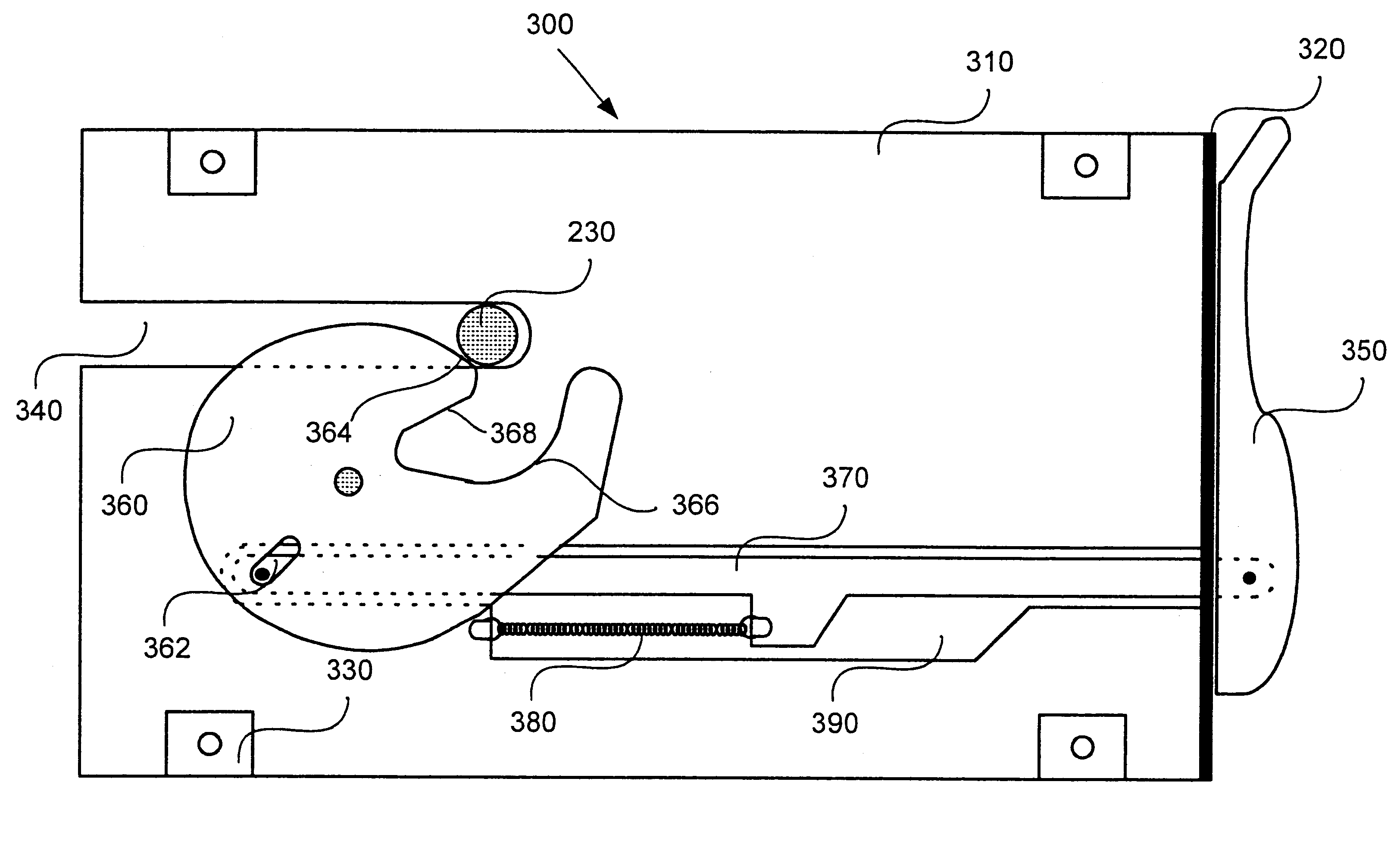
Card carriers consistent with the present invention include a rotating cam having three surfaces which alternately act on a stationary pin in a housing to facilitate insertion, removal, and retention of a circuit card. The cam is rotated by a lever or handle on the front of a faceplate that is attached to the card carrier to securely insert the circuit card into the housing and ease the removal of the circuit card.

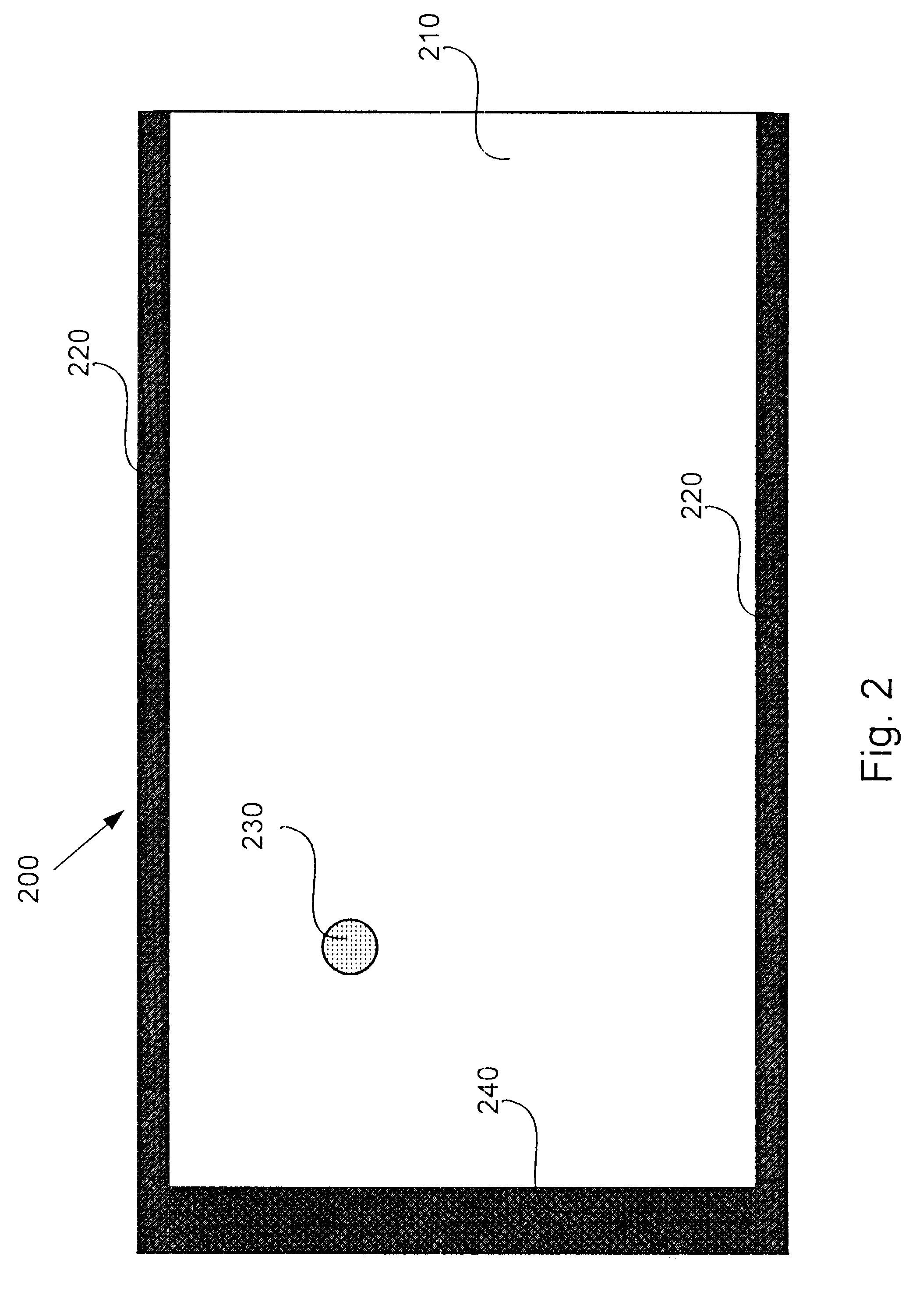
FIG. 2 shows a plan view of receiving hardware 200 consistent with the present invention that may be located in the housing 100. This hardware 200 includes a base plate 210, which is connected to a pair of guides 220 for aligning and guiding a card carrier during insertion. The base plate 210 is ...


PUM


Abstract

A removable apparatus for carrying a circuit board includes a carrying plate having a notch to receive a stationary pin of an enclosure and a faceplate connected to one end of the carrying plate. A rotating cam connects to the carrying plate and acts on the pin to move the apparatus relative to the pin during insertion into and removal from the enclosure. The cam includes two different surfaces, each of which acts to move the apparatus either into or out of the enclosure. A linkage is connected to the cam and extends through the faceplate, connecting to a lever on the exterior of the faceplate. The lever is used to rotate the cam, which in conjunction with the pin provides translational motion either to mate a connector on the circuit board with a corresponding connector in the enclosure or to separate the mated connectors, depending on the direction of rotation.

Description

1. Field of the InventionThe present invention relates generally to a mechanism for holding a circuit board and, more particularly, to mechanisms for inserting and removing a circuit board to / from a housing.2. Description of Related ArtConventional electronic systems typically contain a number of similarly-functioning circuit boards, which may also be referred to as boards or cards. Such a system, shown in FIG. 1, includes a housing 100 containing a back plane, or some other electronic architecture (not shown), for receiving and interconnecting the cards. These cards conventionally plug into connectors located on a back plane or mid plane. The housing 100 typically contains a number of racks 110 to hold the cards. An example of such a system is a rack-mounted communication system which contains a number of communication interface cards.Each circuit card is typically affixed to a card carrier, that fits into corresponding receiving hardware (not shown) in the housing 100. The receivi...

Claims


Application Information

Patent Timeline
IPC IPC(8): H05K7/14H01R13/629
CPCH01R12/7005H05K7/1409H01R13/62938
Inventor HEITKAMP, ROSS SUYDAM
Owner JUMIPER NETWORKS INC
Why Eureka
Try Eureka