Bone reinforcement plate for use on the spine

a bone reinforcement plate and spine technology, applied in the field of bone reinforcement plates, can solve the problems of additional burden on the patient bearing the bone reinforcement plate, cost, trouble,

Inactive Publication Date: 2002-06-18
KUO ROBERT W H
View PDF9 Cites 204 Cited by
  • Summary
  • Abstract
  • Description
  • Claims
  • Application Information

AI Technical Summary

Problems solved by technology

When the conventional bone reinforcement plate (50) is used, too many retainers (screws) are required not only to secure the spine structure, but also to secure the bone reinforcement plate (50) onto the spine (40), which causes an additional burden to the patient bearing the bone reinforcement plate (50).
In conclusion, implanting and maintaining the bone reinforcement plate (50) in position is costly and troublesome.

Method used


Image

  • Bone reinforcement plate for use on the spine
  • Bone reinforcement plate for use on the spine
  • Bone reinforcement plate for use on the spine

Examples


Embodiment Construction

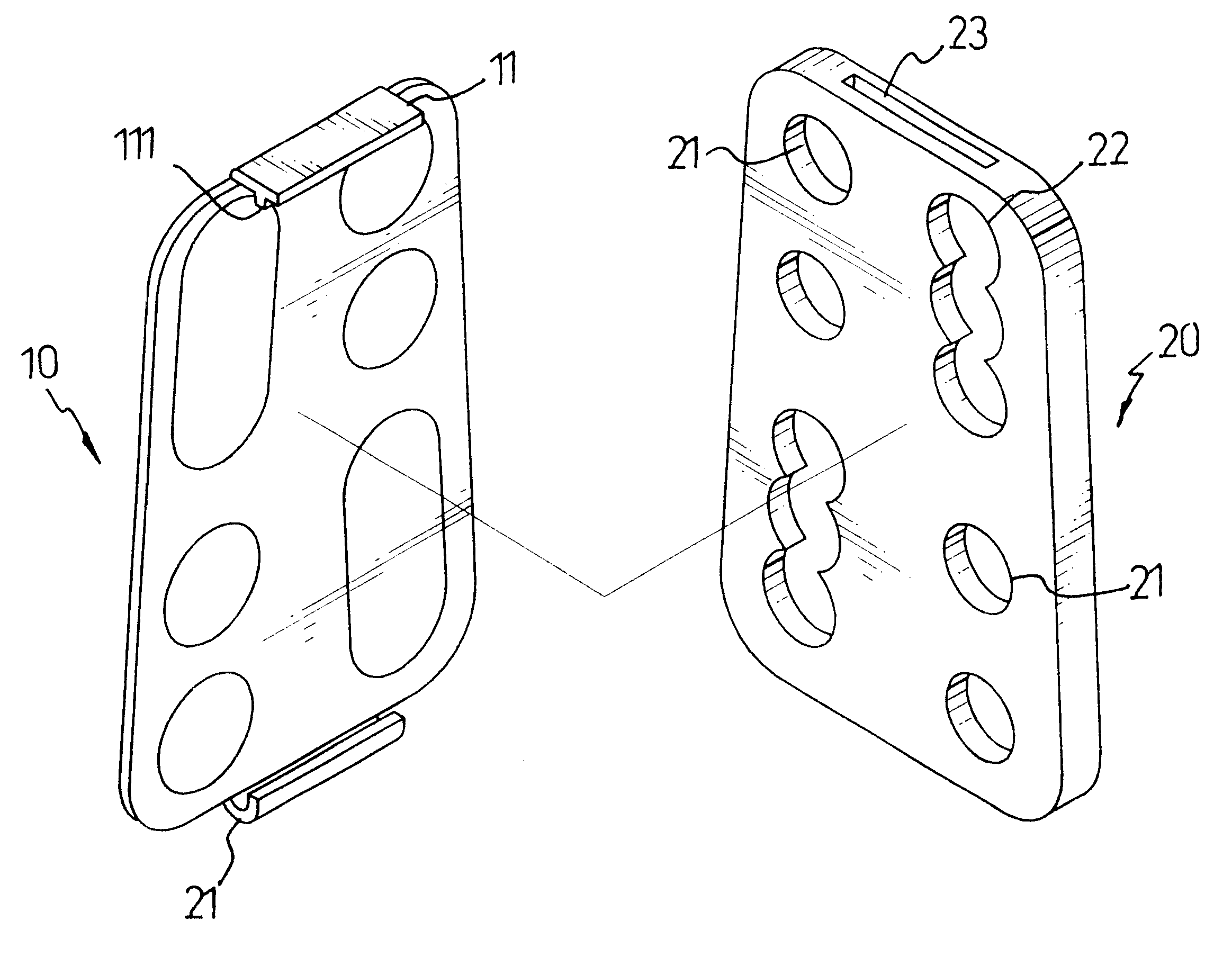
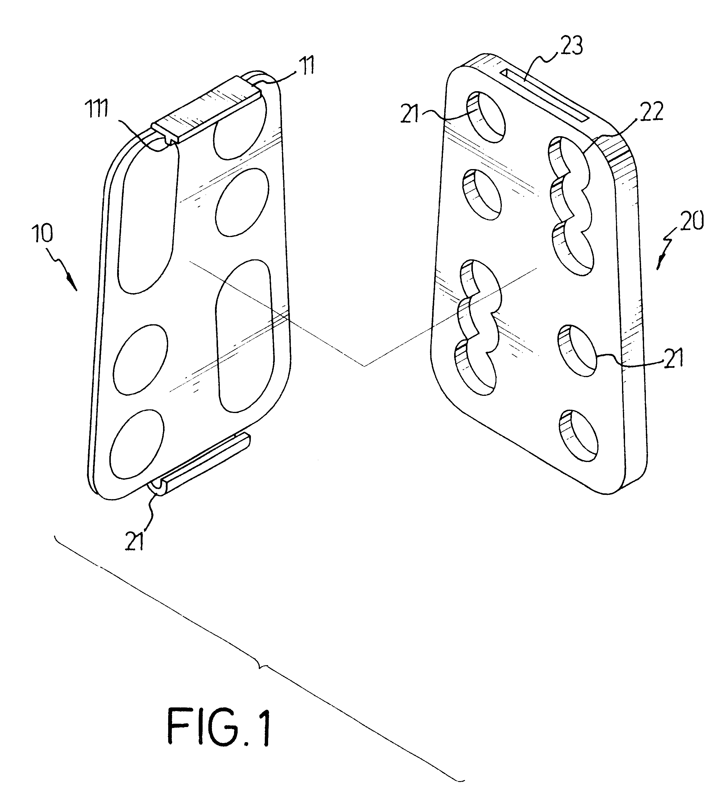
With reference to FIGS. 1 and 2, a bone reinforcement plate (1) in accordance with the present invention has a cover (10) and a base (20).

The cover (10) is detachably connected to the base (20) and has a wing (11) extending perpendicularly to an upper edge of the cover (10). A rib (111) is integrally formed on the wing (111). The cover (1) further has a lower resilient hook (12) formed to oppose the wing (11) and rib (111).

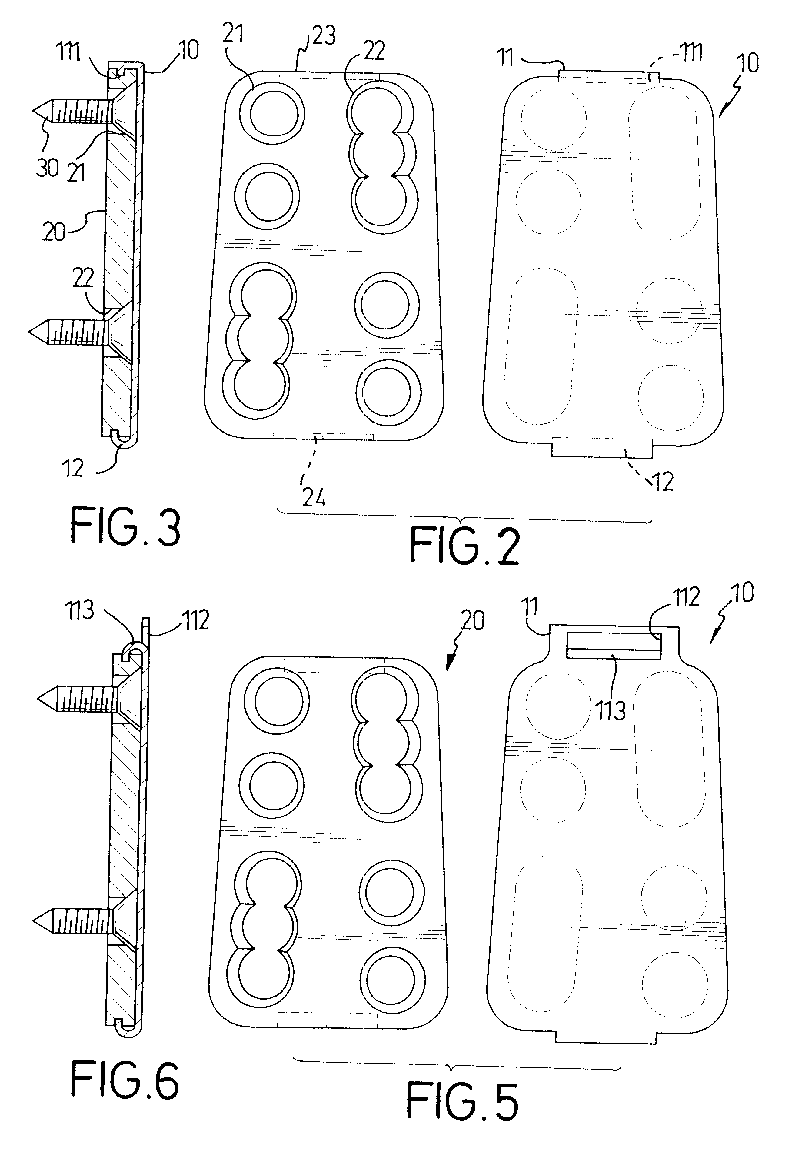
The base (20) has multiple through holes (21), slots (22), an upper recess (23) and a lower recess (24). The upper recess (23) is defined to correspond to the rib (111) on the wing (11) and the lower recess (24) is defined to correspond to the lower resilient hook (12) on the cover (10). Each of the slots (22) is composed of overlapping holes, such that the slot has a wavy inner periphery.

With reference to FIG. 3, when the cover (10) and the base (20) are used, suitable fasteners such as bone screws (30) are inserted into suitable holes (21) and / or slots (22) and ...


PUM


Abstract

A bone reinforcement plate for the spine has a cover and a base detachably engaged with the cover and having through holes and slots. Each slot has a wavy inner periphery. Fasteners are selectively inserted into the through holes and slots and abutted by the cover.

Description

1. Field of the InventionThe present invention relates to a bone reinforcement plate, and more particularly to a bone reinforcement plate especially applicable to the spine.2. Description of Related ArtWith reference to FIG. 7, a conventional bone reinforcement plate (50) is used to reinforce the bone to hold bone fragments in place and prevent further cracking of the bone. The bone reinforcement plate (50) has multiple through holes (51) and slots (52) defined through the bone reinforcement plate (50). On the bone reinforcement plate (50), the holes (51) and slots (52) are in pairs composed of holes-slot combination (A), slot-slot combination (B) and holes-holes combination (C).With reference to FIGS. 8 and 9, when the bone reinforcement plate (50) is used, bone screws (53) with tapered heads (531) are inserted through the through holes (51) and slots (52) and screwed into the spine (40) until the end of the tapered head (531) is flush with bone reinforcement plate (50). The bone s...

Claims


Application Information

Patent Timeline
Patent Type & Authority Patents(United States)
IPC IPC(8): A61B17/70A61B17/68A61B17/80
CPCA61B17/7059Y10S606/902A61B17/8042
Inventor KUO, ROBERT W. H.
Owner KUO ROBERT W H
Why Eureka
Try Eureka