Printing head inspecting device and method for printer

a printing head and inspection device technology, applied in printing, other printing apparatus, etc., can solve the problems of affecting the quality of printed images,

Inactive Publication Date: 2002-07-02
FUJIFILM HLDG CORP
View PDF3 Cites 25 Cited by
  • Summary
  • Abstract
  • Description
  • Claims
  • Application Information

AI Technical Summary

Problems solved by technology

If the ink jet printer is repeatedly used, choking of ink is likely to occur in the nozzles.
It is likely that an ejected amount of ink decreases.
This causes streaks or other unevenness in color or density to occur in a printed image.
It is, however, likely that an operator discovers the choking of ink too late.
Images may be printed at a low quality due to the failure.
However, if the printer is used commercially at a printing shop, failure in operation of the nozzles may cause serious problem due to occurrence of a great number of failing prints to be produced.
There is a problem in that designation of failing nozzles becomes more difficult according to the high density of the nozzles.

Method used


Image

  • Printing head inspecting device and method for printer
  • Printing head inspecting device and method for printer
  • Printing head inspecting device and method for printer

Examples


Embodiment Construction

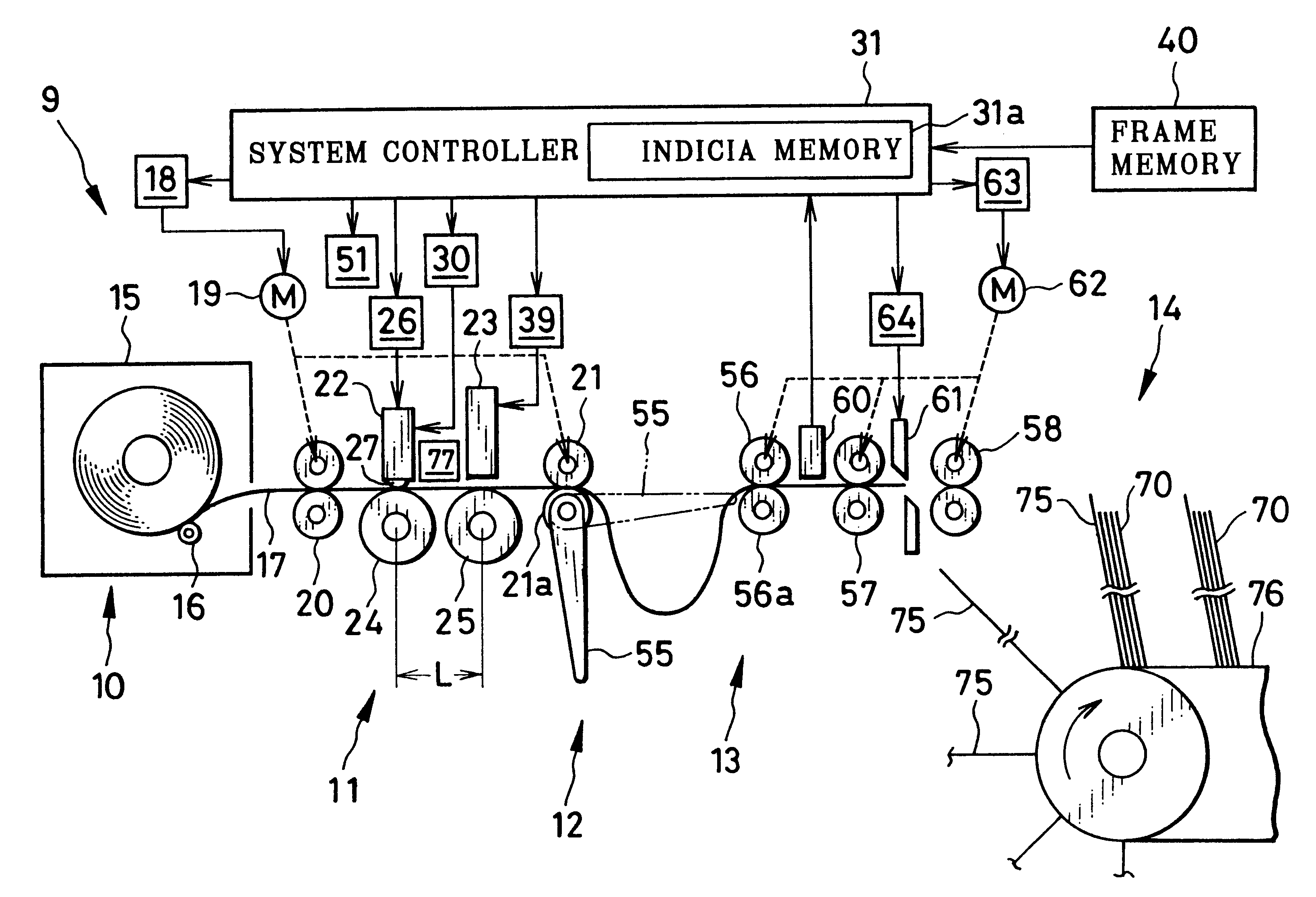
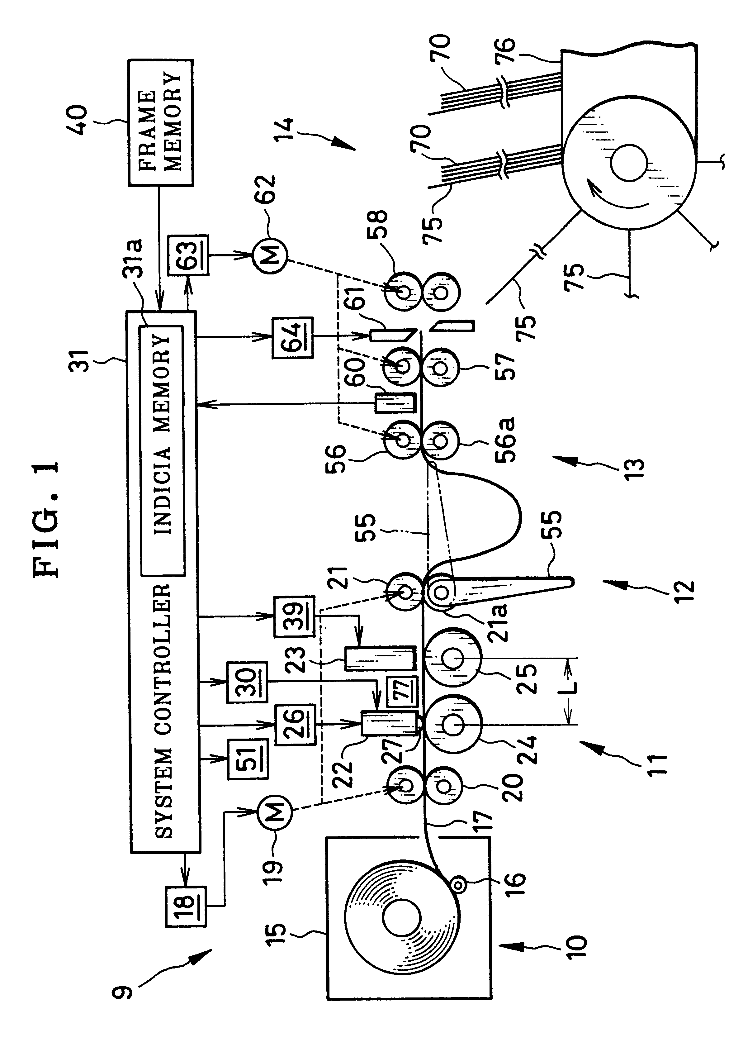
In FIG. 1, an ink jet printer 9 is illustrated, and is constituted by a sheet supply unit 10, an image forming component 11, a sheet reservoir 12, a cutter 13 and a sorter 14. A recording sheet magazine 15 is provided with a supply roller 16, which is rotated by the sheet supply unit 10 to unwind and advance continuous recording sheet 17 as recording material from the recording sheet magazine 15. The continuous recording sheet 17 is supplied to the image forming component 11. In the present embodiment, the continuous recording sheet 17 has a width of approximately 210 mm according to the A4 format of 210.times.297 mm. Each print to be obtained from the continuous recording sheet 17 has the A4 format. Of course, the width of the continuous recording sheet 17 and the size of each image frame may be changed in a suitable manner.

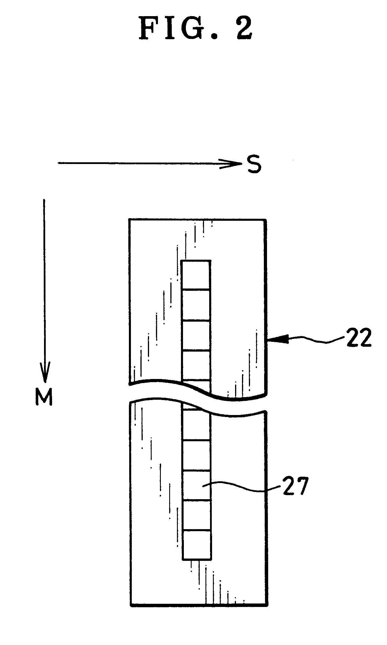
The image forming component 11 is constituted by feeder roller sets 20 and 21, a preheating thermal head 22, and an ink jet printing head 23. The feeder roller ...


PUM


Abstract

An ink jet printer includes an ink jet printing head, having plural recording elements arranged in a main scan direction. Feeder roller sets move continuous recording sheet relative to the printing head in a sub scan direction, to print an image to the continuous recording sheet. A printing head inspecting device for the printer is provided. A controller causes the feeder roller set to set first and second line positions of the continuous recording sheet sequentially at the printing head. While one of the first and second line positions is set at the printing head, the controller simultaneously drives recording elements in one of first and second groups into which the recording elements are grouped in the printing head, to print one check dot train to the continuous recording sheet. Thus, two check dot trains are printed in the first and second line positions. Each of the first and second groups includes plural recording elements intermittently arranged in the printing head. An inspection sensor detects the two check dot trains, to inspect whether the recording elements print at intended density.

Description

1. Field of the InventionThe present invention relates to a printing head inspecting device and method for a printer. More particularly, the present invention relates to a printing head inspecting device and method for a printer capable of quickly discovering failure in a printing head.2. Description Related to the Prior ArtAn ink jet printer is known, and includes an ink jet printing head, which includes a group of nozzles for ejecting ink to recording material to print an image thereto. If the ink jet printer is repeatedly used, choking of ink is likely to occur in the nozzles. It is likely that an ejected amount of ink decreases. Furthermore, no ink may be ejected. This causes streaks or other unevenness in color or density to occur in a printed image.In general, an operator observes the printed image, and if there are streaks with unevenness in color or density, changes over the ink jet printer to a head cleaning mode. The printer is cleaned to eliminate the choking of ink or ab...

Claims


Application Information

Patent Timeline
Patent Type & Authority Patents(United States)
IPC IPC(8): B41J15/00B41J2/01
CPCB41J2/01B41J15/005
Inventor MATSUMOTO, NOBUOKITO, EIICHIKANEKO, KIYOTAKAHOSONO, YASUYUKI
Owner FUJIFILM HLDG CORP
Why Eureka
Try Eureka