
Ink supply tank for an inkjet print head

a technology of inkjet printing and supply tank, which is applied in printing and other directions, can solve the problems of a number of individual components in the supply tank, and achieve the effects of reducing labor intensity, reducing labor intensity, and reducing labor intensity

Inactive Publication Date: 2002-05-14
ARTECH DESIGN PRODN & PLASTIC
View PDF18 Cites 67 Cited by
  • Summary
  • Abstract
  • Description
  • Claims
  • Application Information

AI Technical Summary

Benefits of technology

It is also advantageous if the actuating elements have a force-increasing transmission acting on the pressure plunger. A force-multiplying transmission of this type can be designed as a lever transmission, for example. This contains, for example, simple and double levers and is used to convert the actuating force exerted by the drive element, i.e., the printer's actuating cams, into a larger pressing force by the pressure plunger. It is thus possible to match the given stroke and actuating force to the pressing force of the pressure plunger in the best possible way so that the required ink overpressure is always built up.
It is also advantageous that the actuating elements have spring elements that compress the ink reservoir in a spring-preloaded fashion. For example, these spring elements are configured in such a way that when the ink supply tank according to the invention is inserted into the corresponding seat in the printer, they are pressed against an abutment placed there. As a result, they exert a predetermined compressive strain on the ink reservoir, which by itself leads to the generation of a minimum ink overpressure in the ink supply lines. All that is then necessary in order to generate the operating overpressure is the exerting of an additional force by the printer's actively triggered drive elements. This is especially helpful for complete utilization of the volume of ink, and ink pressure that is adequate at all times.
With regard to the pressure plunger, it is preferable that placed behind the foil bag is a fixed abutment that is formed to correspond to the pressure plunger. What is meant by this is that the pressure plunger is, for example, convex in shape, while the abutment is correspondingly formed concavely, so that when the pressure plunger presses against the abutment, the ink contained in the foil bag located between them is forced out with nothing left behind, i.e., it is pressed into the ink supply lines. In this way, a practically complete utilization of the ink contained in the ink bag is obtained.
An advantageous further development of the invention provides that the pressure-generating device is equipped with a pressure pump, which is coupled to the actuating elements and which, when activated, provides the interior of the ink reservoir with overpressure. For example, it can be a simple, small diaphragm air pump that either provides the ink reservoir with air pressure directly--or--fills a positive displacement body or balloon with overpressure.
In the simplest case, the measuring elements can have switching contacts that, for example, close a circuit when the ink reservoir collapses or is compressed as it empties. The use of inductive or capacitive or optical sensors or something similar has the advantage that a continuous detection of the amount of ink can be carried out with little effort. All of the embodiments have the advantage in this regard that a reliable indication of the amount can be realized with little effort. This applies in particular to embodiments in which the ink reservoir is compressed by an actively actuated pressing plunger, but is not limited to such an embodiment, i.e., it can also be implemented with conventional ink supply tanks with non-loaded or springpreloaded ink reservoirs.

Problems solved by technology

One significant disadvantage of the known ink supply tank with active ink delivery, however, is the fact that the pump mechanism for ink delivery is made up of a number of individual components.

Method used


Image

  • Ink supply tank for an inkjet print head
  • Ink supply tank for an inkjet print head

Examples


Embodiment Construction

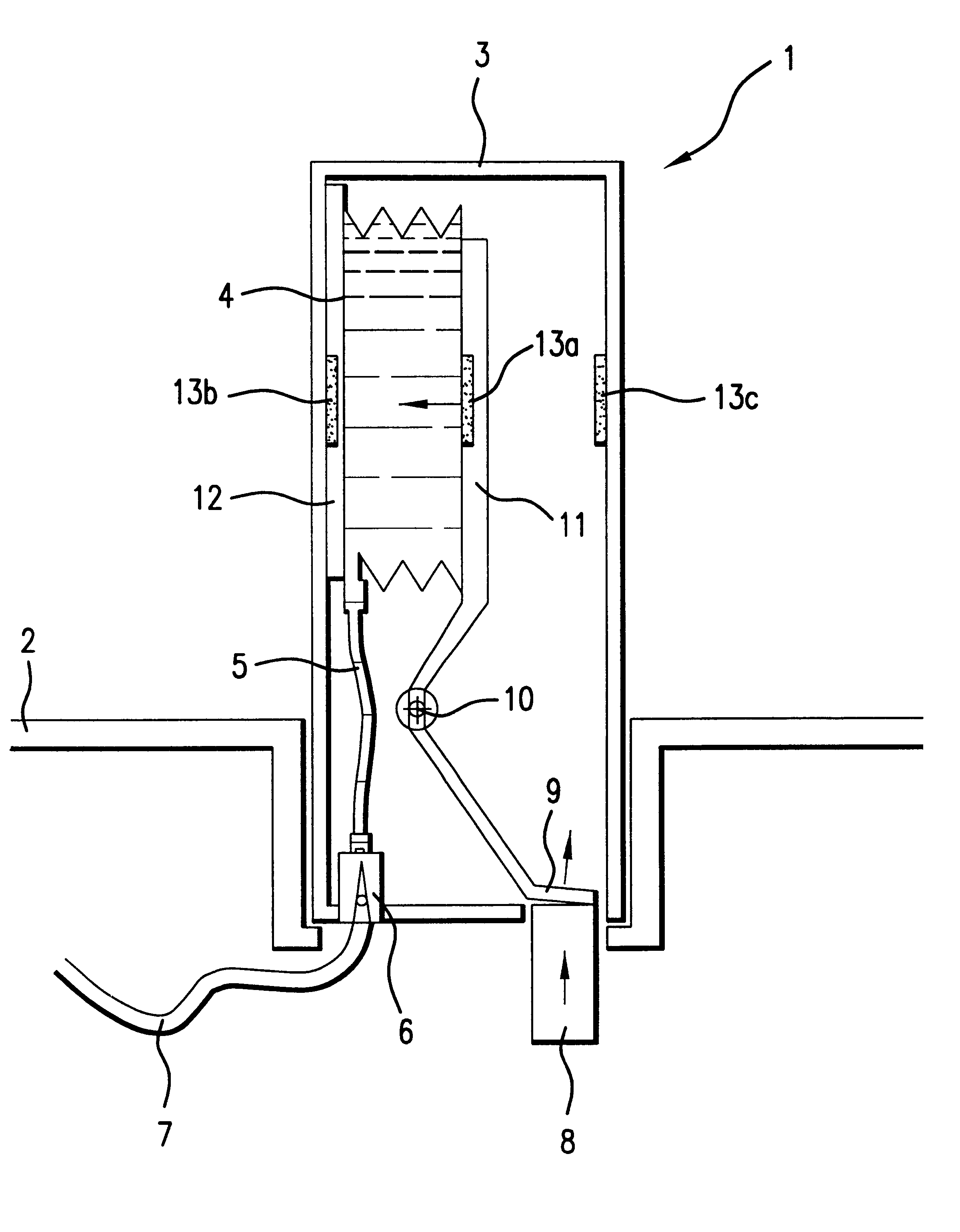
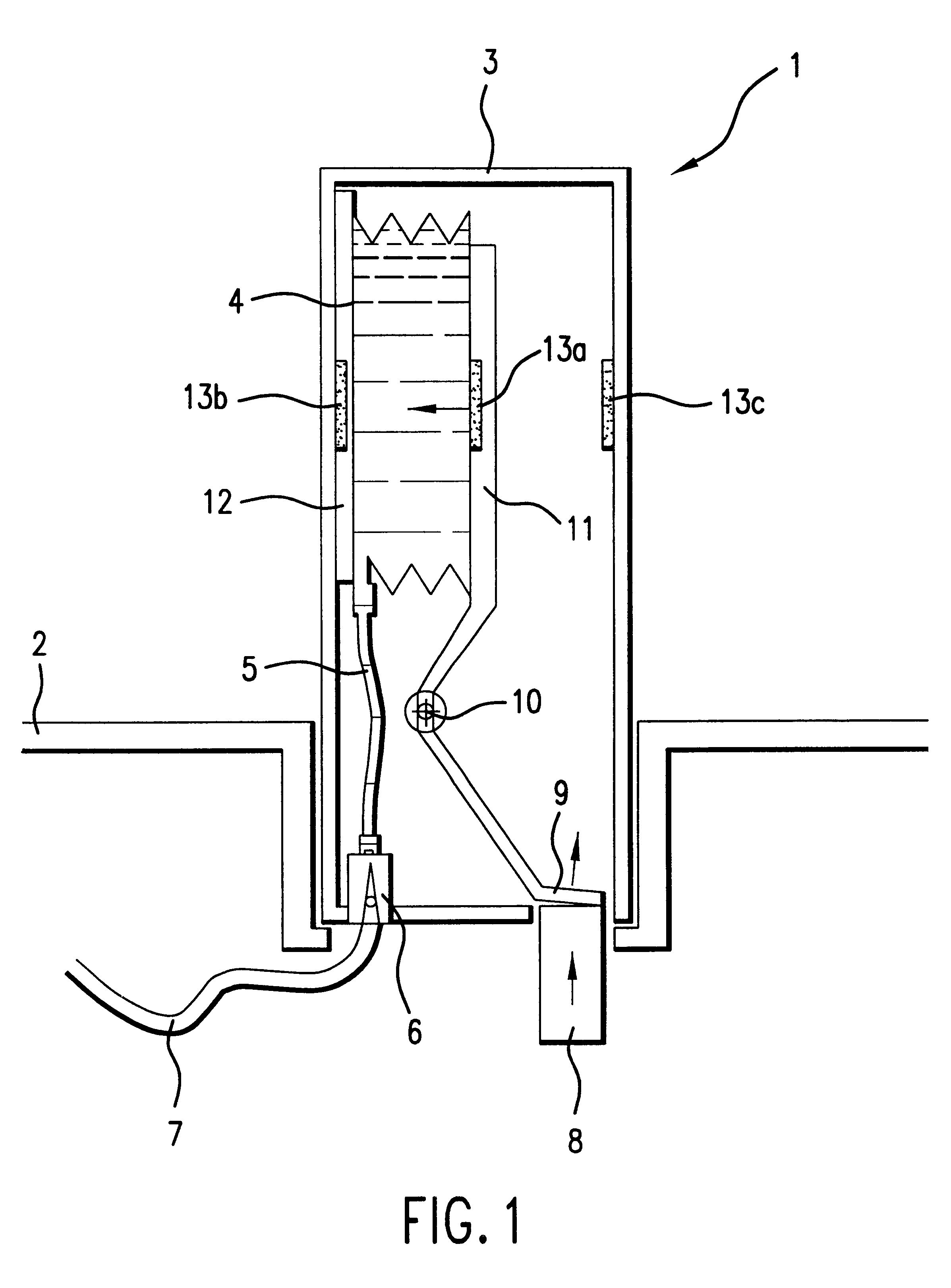
In the schematic cross-section representation according to FIG. 1, an ink supply tank according to the invention is designated by reference number 1. It is placed in the corresponding holding well of an inkjet printer 2, which is only indicated.

The ink supply tank 1 has a housing 3 in which is placed an ink reservoir 4 completely filled with ink. This ink reservoir 4 is configured as a bellows-like foil bag, which can be compressed in the direction of the white arrow. Its interior is connected by means of a connecting tube with a connecting means that is accessible from outside, e.g., a septum or a connecting valve. An ink supply line 7 that leads to the inkjet print head of the printer 2 can be connected to this connecting means 6 as shown.

Designated by reference number 8 is a drive element of the printer 2, which element is shown in its idle position and which can be displaced in the direction of the arrow by a motor-powered driving means. Through an opening in the housing 3, this...


PUM


Abstract

The present invention pertains to an ink supply tank for an inkjet print head that can be installed in fixed fashion in an inkjet printer, having an ink reservoir that can be connected to an ink supply line leading to an inkjet print head, and having an ink delivery device that has actuating elements accessible from the outside, which can be brought into active engagement with corresponding, motor-powered drive elements of the inkjet printer, in which the ink delivery device feeds ink into the ink supply line at overpressure upon actuation of the actuating elements. In order to reduce the manufacturing effort and ensure a high level of functional reliability with an ink supply tank of such a type, the invention suggests that the ink delivery device have a pressure-generating device that acts on the ink reservoir and is coupled with the actuating elements, and that provides the ink reservoir with overpressure when the actuating elements are driven.

Description

The present invention pertains to an ink supply tank for an inkjet print head that can be installed in fixed fashion in an inkjet printer, having an ink reservoir that can be connected to an ink supply line leading to an inkjet print head, and having an ink delivery device that has actuating elements accessible from the outside, which can be brought into active engagement with corresponding, motor-powered drive elements of the inkjet printer, whereby the ink delivery device feeds ink into the ink supply line at overpressure upon actuation of the actuating elements.1. PRIOR ARTA central component of the inkjet printer is the inkjet print head, which can be positioned relative to the printable area by means of suitable mechanicals and which creates the printed image through the controlled discharge of ink from a multiplicity of fine print nozzles. The continuous supplying of the print head with ink takes place from an ink reservoir that holds a rather large quantity of ink. For simple...

Claims


Application Information

Patent Timeline
IPC IPC(8): B41J2/175
CPCB41J2/17503B41J2/17513B41J2/17556B41J2/17566B41J2/17523B41J2002/17586
Inventor MICHELE, HELMUTKLEIN, DIRKBUSCH, PETER
Owner ARTECH DESIGN PRODN & PLASTIC
Learn More