Antenna for radio telephone

a radio telephone and antenna technology, applied in the direction of antennas, pivotable antennas, antenna details, etc., can solve the problems of not being able to be retracted into the case at the time of retraction, prone to mechanical or electrical noise, and risk of deterioration of the retaining member 91 retaining power

Inactive Publication Date: 2002-07-02
MINEMITSU DENSHI
View PDF13 Cites 32 Cited by
  • Summary
  • Abstract
  • Description
  • Claims
  • Application Information

AI Technical Summary

Problems solved by technology

Since it is common to manufacture the conductor 71 using a member of small diameter having good elasticity, the arrangement of a helical coil 81 having large mass at the distal end thereof creates susceptibility to vibration due to external pressure, the amplitude thereof being large, creating susceptibility to mechanical or electrical noise and posing the risk that the retaining power of the retaining member 91 may deteriorate.
Further, the connecting member 72 of this antenna of Conventional Art Example 1 has a problem in terms of flexural strength, and depending on the length thereof breakage may occur with repeated flexing.
Improving the flexural durability requires means such as lengthening the length, etc., but by so doing the total length of the rod-shaped antenna 70 will become physically long, creating the problem of not being retractable into the case at the time of retraction.
Further, the antenna of Conventional Art Example 2 has the problem that the electrical length of the rod-shaped antenna 74 is long when retracted, so that it cannot be physically accommodated within the increasingly more compact cases of recent years.
However, this runs counter to the trend of compactness and lighter weight on the part of radio telephones.
However, the antenna of Conventional Art Example 3 has the problem of being impossible to realize in terms of antenna engineering.
Further, since the means for canceling out the inductive reactance+jX of the rod-shaped antenna is unclear, base impedance of Z=50.+-.j0 on the part of the antenna cannot be realized, and thus the antenna is not realizable.
Specifically, in light of the wide service frequency band assigned to portable radio telephones these days, adapting to wider bandwidth through impedance matching means that creation of the aforementioned free electrostatic capacitance will make it difficult to adapt to the wider bandwidth.
Another problem associated with creation of free electrostatic capacitance is lowered gain and sensitivity.

Method used


Image

  • Antenna for radio telephone
  • Antenna for radio telephone
  • Antenna for radio telephone

Examples


Embodiment Construction

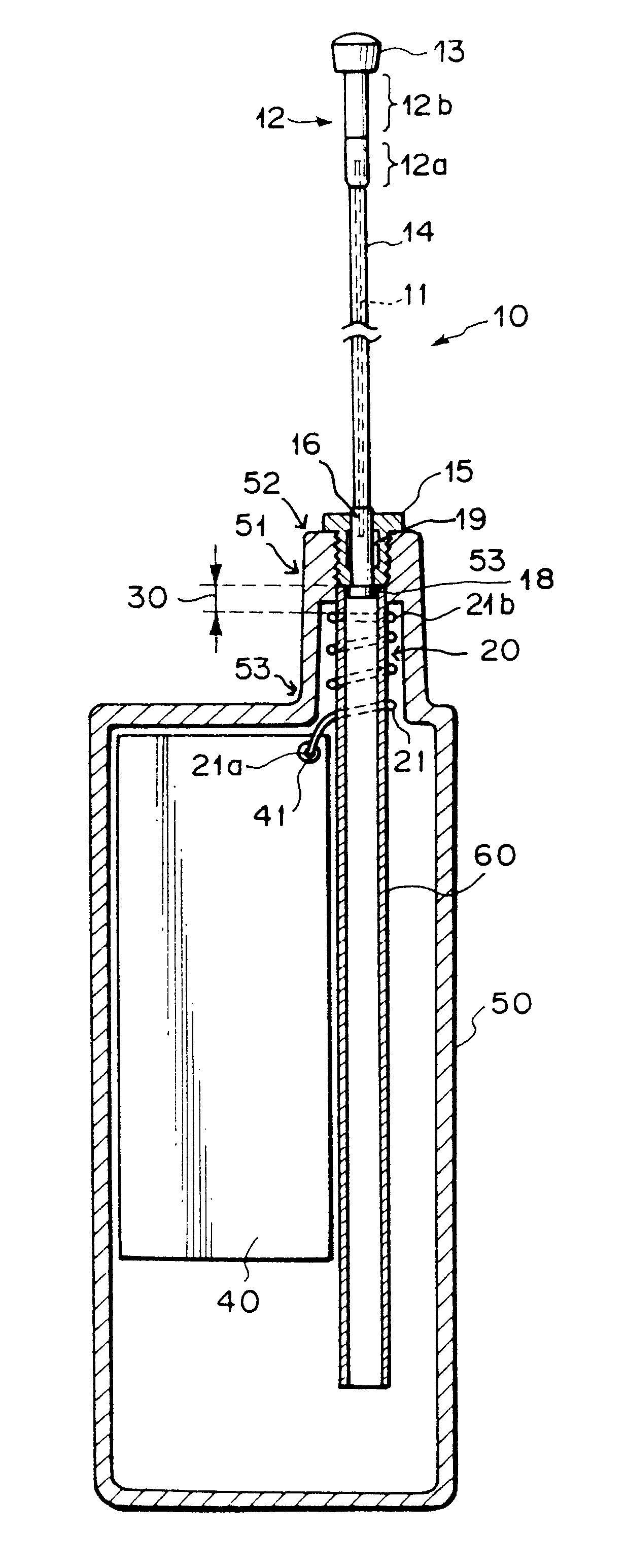
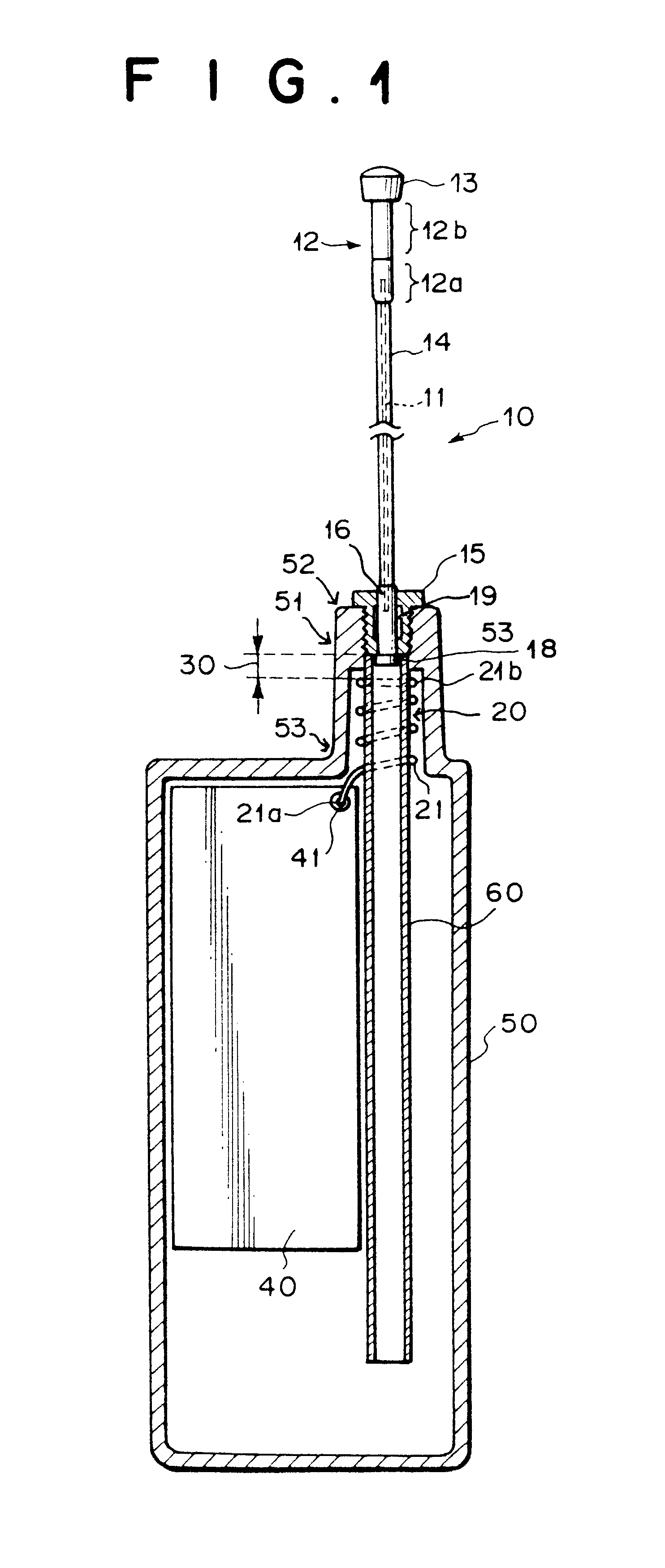
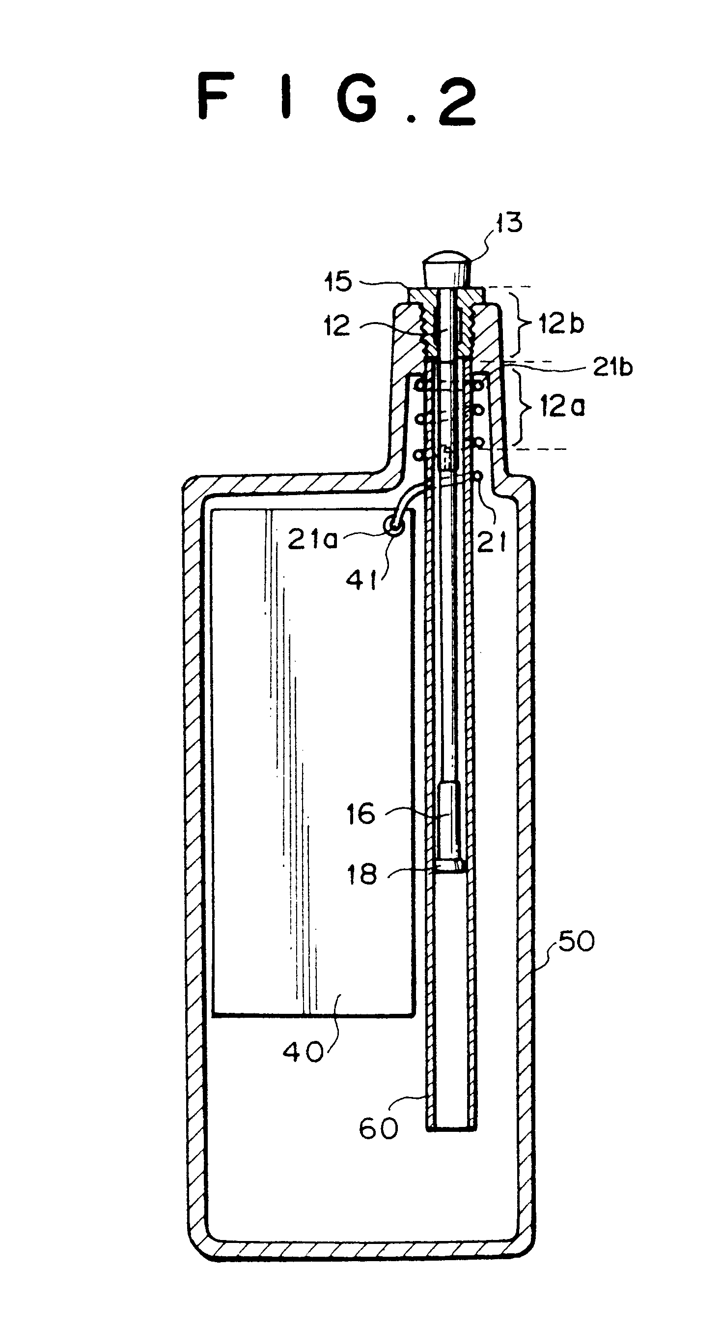
or 2 the metal retaining member 91 etc. is arranged in proximity to the power supply portion 41, thus creating between the retaining member 91 and the power supply portion 41 a large free electrostatic capacitance that cannot be ignored in terms of antenna engineering, and resulting in impaired impedance matching. Specifically, in light of the wide service frequency band assigned to portable radio telephones these days, adapting to wider bandwidth through impedance matching means that creation of the aforementioned free electrostatic capacitance will make it difficult to adapt to the wider bandwidth. Another problem associated with creation of free electrostatic capacitance is lowered gain and sensitivity.

Further, in the event that the radio telephone should be accidentally dropped on the floor in a state with the rod-shaped antenna retracted within the case 50, a concentrated impact load will be applied to the base of the helical antenna 80, creating the risk that the helical anten...


PUM


Abstract

Provides an antenna for a radio telephone whereby, in a state wherein the rod-shaped antenna is extended to outside the case of the radio telephone, the effects of the human body are negligible and emission of radio waves at an angle close to the horizontal direction is possible, and in a state wherein the rod-shaped antenna is retracted within the case, no unwanted radiation is produced. For this purpose, a helical antenna 20 having an electrical length of lambd / 4 and a rod-shaped antenna 10 extendable and retractable with respect to the case through the hollow central portion of the helical antenna 20 and having an electrical length of about 3lambd / 8 and inductive reactance are electrically coupled by means of an electrostatic coupling portion 30 having capacitive reactance such that, in the state wherein the rod-shaped antenna 10 is extended from the case 50, the inductive reactance of the rod-shaped antenna 10 is cancelled out. The length of the bottom portion 12a of the connecting member 12 is set to a length such that when the rod-shaped antenna 10 is retracted within the case 50, the bottom portion 12a of the connecting member 12 passes through the helical coil 12 over the entire length thereof, severing electrical coupling between the helical antenna 20 and the rod-shaped antenna 10.

Description

1. Field of the InventionThe present invention relates to an antenna for a radio telephone, and more particularly to an antenna for a radio telephone for use in a cellular, PHS (Personal Handy Phone System), or other mobile phone system.2. Description of the Related ArtToday, cellular, PHS, and other mobile phone systems enjoy widespread use. The radio telephones (telephones) used in such systems have in recent years become increasingly more compact and lightweight, creating a need to make the antennas used therefor smaller in association with the smaller size and lighter weight of the radio telephones.An extendible / retractable antenna used by extending a rod-shaped antenna from the case of the radio telephone to communicate in locations where electric field strength is weak, and retracting the rod-shaped antenna into the case of the radio telephone to make it convenient to hold and walk when being carried about, and that stands by to receive calls with a helical antenna alone is co...

Claims


Application Information

Patent Timeline
Patent Type & Authority Patents(United States)
IPC IPC(8): H01Q1/24H01Q1/08H01Q1/22
CPCH01Q1/084H01Q1/244
Inventor EGASHIRA, YOSHIMI
Owner MINEMITSU DENSHI
Why Eureka
Try Eureka