Slope block

a technology of slope block and slop block, which is applied in the direction of height/levelling measurement, instruments, surveillance instruments, etc., can solve the problem of no convenient adjustment means availabl

Inactive Publication Date: 2002-08-06
PRECISION DESIGNED PRODS
View PDF10 Cites 42 Cited by
  • Summary
  • Abstract
  • Description
  • Claims
  • Application Information

AI Technical Summary

Problems solved by technology

However, problems and difficulties have been encountered which are due to the fact that different angles are required and there is no convenient adjustm...

Method used


Image

  • Slope block
  • Slope block

Examples


Embodiment Construction

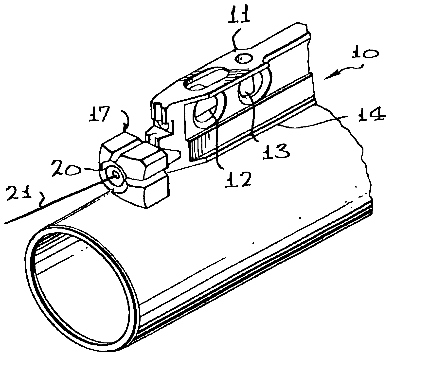
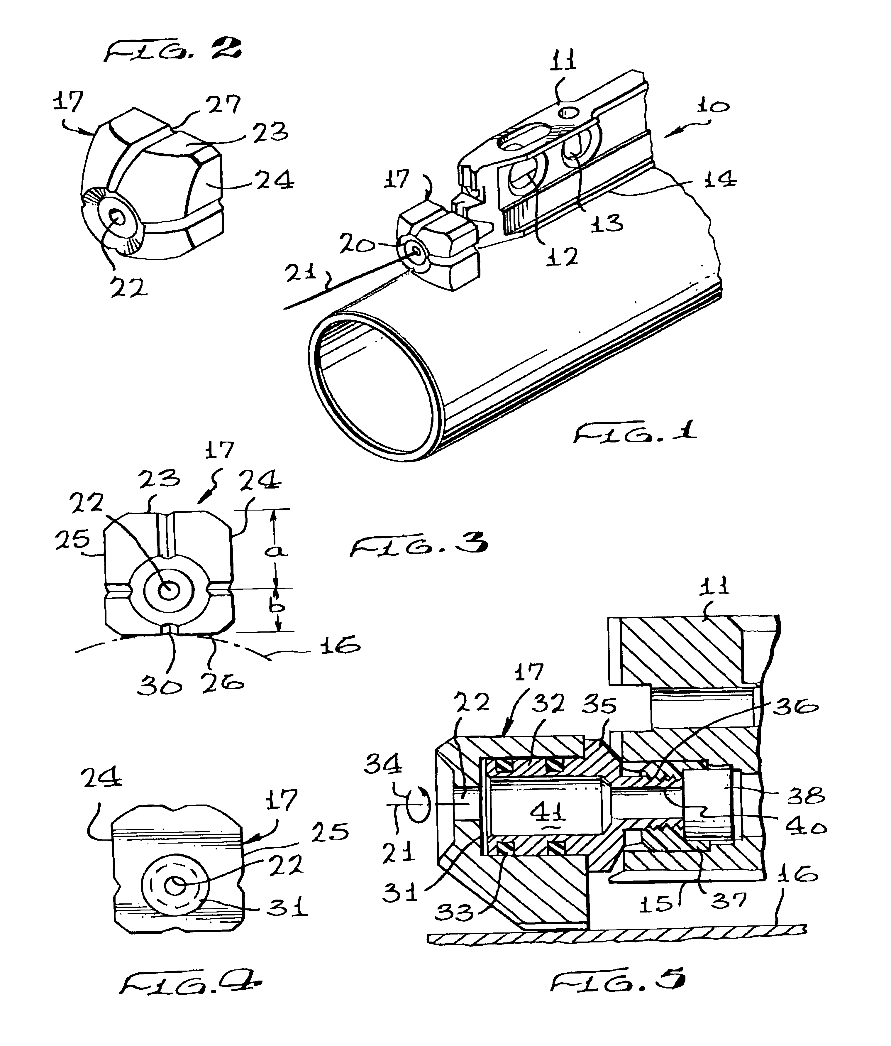
Referring to FIG. 1, the novel slope block assembly incorporating the present invention is illustrated in the general direction of arrow 10, which includes an elongated level 11 having tubular indicators 12 and 13 exposed for visual observation in order to determine a desired level of parallelism or a given angle relationship. Each indicator is a tub containing a fluid which is preferably colored so that an observer can readily determine vertical, horizontal or any angular disposition of the fluid. The level also includes an undersurface 14 that is relatively flat so that it may be placed on a flat surface for orientation purposes. However, the surface is also provided with a linear groove shown in FIG. 5 by numeral 15 so that the level can be supported on a round or circular surface such as tube 16. The end of the level 11 mounts a slope block 17 that is available to elevate one end of the level to provide a desired angle for the beam 21. The front face of the block includes a rece...


PUM


Abstract

A slope block assembly having a bubble level with an eccentrically mounted slope block detachably carried on one end of the level. The slope block has an offset turning axis with a plurality of supporting surfaces, all located at different distances from the turning axis. The support surfaces cooperate with an undersurface or support point on the level to direct a laser beam at a desired angle with respect to a round or flat reference surface. Grooves are provided on the slope block support surfaces as well as on the level undersurface to support the level and slope block assembly on a round or curved reference surface.

Description

1. Field of the InventionThe present invention relates to the field of levelling devices, and more particularly to a novel slope block which attaches to a laser level allowing for quick, easy and perfect projection of a laser beam whereby the slope or pitch of the level can readily be selectively adjusted.2. Brief Description of the Prior ArtIn the past, it has been the conventional practice to place a level on a surface in order to project a laser beam in a driven direction so that the beam is properly aligned and in parallel relationship with respect to the surface. At times, it is desirable to elevate one end of the level with respect to the surface for a given number of degrees so that the projected laser beam is angularly disposed with respect to the flat surface on which the level resides. In this selective or adjustment capacity, a plurality of pins or other elements are employed for raising the end of the level a given distance above the flat surface so that the generated la...

Claims


Application Information

Patent Timeline
IPC IPC(8): G01C15/00
CPCG01C15/008
Inventor WEBB, JAMES
Owner PRECISION DESIGNED PRODS
Why Eureka
Try Eureka