Elastic dental device

a dental device and elastic technology, applied in the field of dental tools and devices, can solve the problems of inconvenient application for dentists, inability to properly conform to the desired shape of plastic cavity filling materials, and inability to place them in the tooth,

Inactive Publication Date: 2002-08-20
HUGHES THOMAS E
View PDF11 Cites 39 Cited by
  • Summary
  • Abstract
  • Description
  • Claims
  • Application Information

AI Technical Summary

Problems solved by technology

It is necessary to use this technique when a cavity is located between adjacent teeth and there is insufficient lateral support for the filling material.
It is well known in the field that the space or gap between two adjacent teeth at the gum line is typically not uniform in size and usually has a substantial inverted v-shape.
Without the use of the matrix band, the plastic cavity filling material would not properly conform to the desired shape and could not be placed in the tooth.
One problem with the use of the matrix band 11 is that it is made of a somewhat flexible material and the outer side walls of teeth are not typically vertical and usually have a curved outward bias.
One problem with existing conventional dental wedge designs in use today is that they are typically not very convenient for a dentist to apply.
Furthermore, conventional dental wedges do not provide uniform force to the base of the matrix band structure.
As a result, the use of the conventional dental wedges in fitting a matrix band to a patient's tooth does not result in the proper seal and fit for the compound contours of natural teeth that is typically desired.
This is due to the non-elastic nature of most conventional dental wedge designs.
Accordingly, the filling material does not necessarily have the desired form fit and does not always conform

Method used


Image

  • Elastic dental device
  • Elastic dental device
  • Elastic dental device

Examples


Embodiment Construction

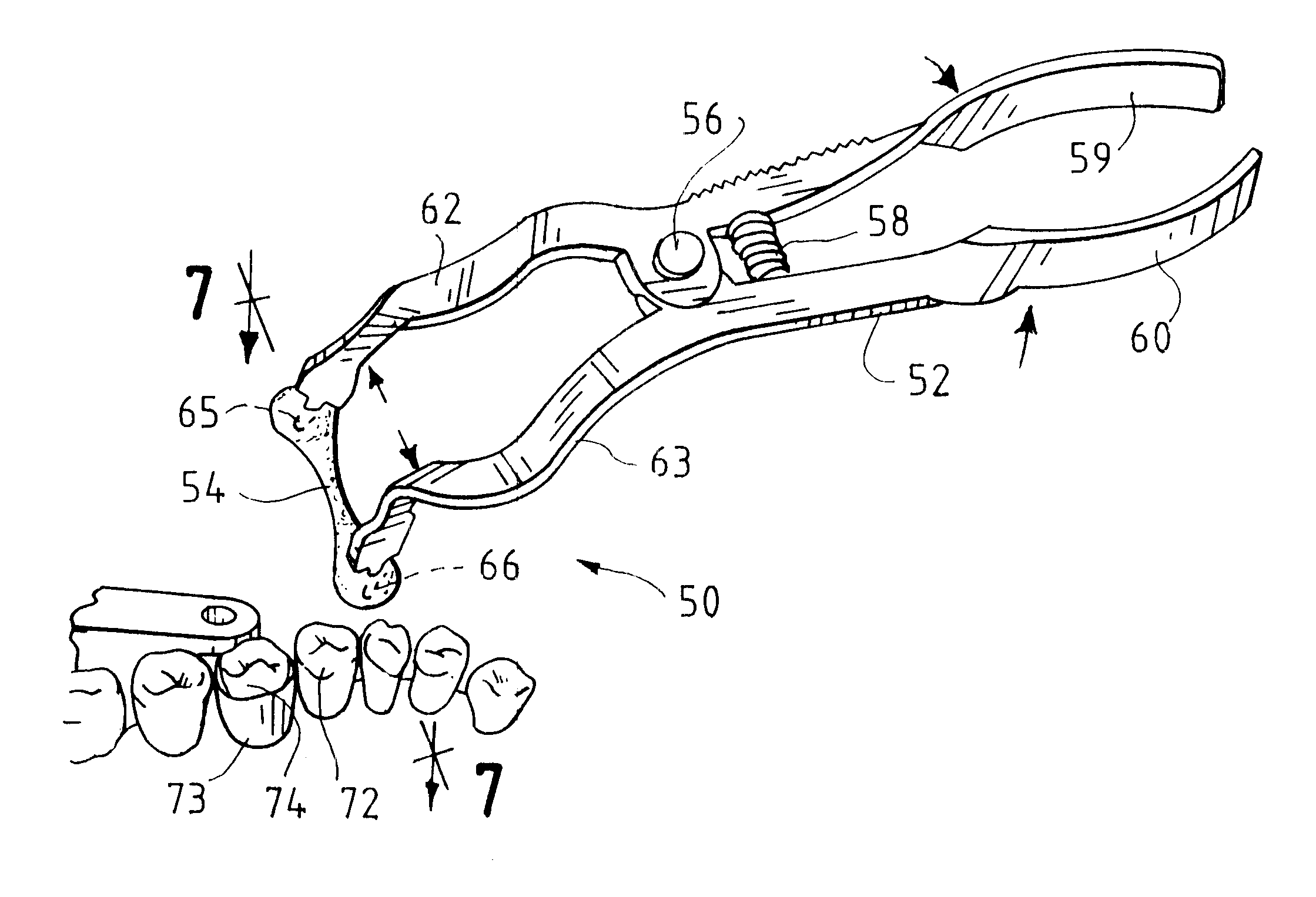
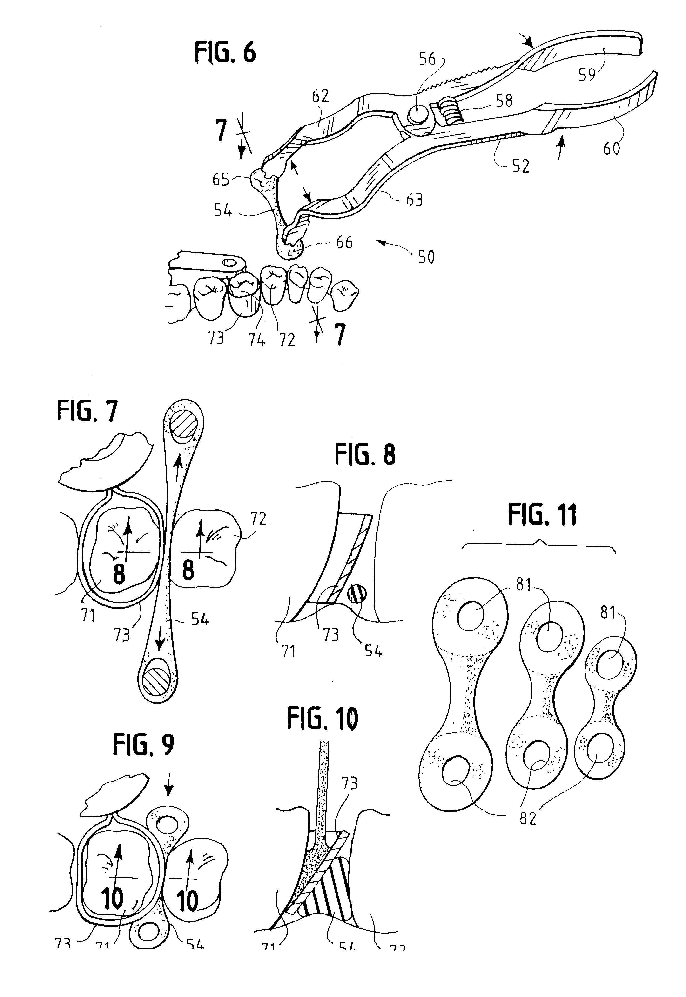
FIG. 6 illustrates a first preferred exemplary embodiment of the present invention which is shown generally at 10. As shown in FIG. 6, a stretching tool 52 provides a force which pulls on opposite ends of an elongated elastic member 54. As a result of the stretching of elastic member 54 the central portion of the elastic member 54 becomes much thinner. In the preferred exemplary embodiment, through application of the stretching force a central portion of the elongated elastic member 54 becomes very thin and is preferably approximately the thickness of dental floss.

Stretching tool 52 employs a central hinge 56 and a compressible spring 58. Inward force on handles 59 and 60 results in outward motion of stretching support members 62 and 63. As noted above, in the preferred exemplary embodiment, the stretching tool 52 is a conventional dental dam forceps as is known in the art. The tips of stretching support members 62 and 63 have protrusions 65, 66 for engaging corresponding holes or o...


PUM


Abstract

Structures and methods are disclosed which may be used for applying force to the base of a matrix band or cavity filling material mold during a cavity filling procedure. In a preferred exemplary embodiment of the present invention, a unitary body of elastic material is stretched preferably by applying force in opposite directions to the opposite ends of the unitary body such that a central portion of the body of material is thinned. The thinned portion of the unitary body may then be easily inserted in the space between two adjacent teeth next to the base of a matrix band or cavity filling material mold. After the unitary body has been inserted into the space between two adjacent teeth next to the base of the matrix band or cavity filling material mold, the force which has been applied to the opposite ends of the unitary body is then removed. As a result, the previously stretched elastic unitary body contracts and becomes thicker in its central portion that had been previously thinned. The contraction and thickening of the unitary body in the space between adjacent teeth fills this space and applies and outward force to the walls of this cavity. Accordingly, the contracted unitary body applies a force on the base of the matrix band or cavity filling material mold which forces the base of the matrix band or filling material mold adjacent to the base of the tooth to be filled.

Description

1. Field of the InventionThe present invention relates generally to the field of dental tools and devices as well as the procedures for the efficient utilization of these tools. More specifically, the present invention is directed to a novel elastic dental wedge for use in cavity filling procedures which provides more uniform support for a matrix band or cavity filling material mold. The devices and methods of the present invention are both simple to use and the improved dental wedge may be quickly and easily inserted and removed.2. Description of the Related ArtDental wedges are conventional devices that have been around for many years in a variety of different well-known configurations. Those skilled in the art of dentistry will recognize that dental wedges are currently used in cavity filling procedures and are specifically used when cavity filling material is to be placed in the interproximal portion of a tooth. In such circumstances, it is necessary to provide additional suppor...

Claims


Application Information

Patent Timeline
IPC IPC(8): A61C5/12A61C5/00
CPCA61C5/125A61C5/85
Inventor HUGHES, THOMAS E.
Owner HUGHES THOMAS E
Why Eureka
Try Eureka