Endoluminal graft

a technology of endoluminal grafts and aorta, which is applied in the field of medical devices, can solve problems such as problems such as problems such as problems such as the incision of such grafts into aorta or other body lumens, and achieve the effect of small structural strength and appropriate structural strength (and flexibility)

Active Publication Date: 2006-09-19
COOK MEDICAL TECH LLC +1
View PDF16 Cites 189 Cited by
  • Summary
  • Abstract
  • Description
  • Claims
  • Application Information

AI Technical Summary

Benefits of technology

[0038]Hence, according to one embodiment of this invention, it is proposed that the graft be a synthetic material tube where the walls of the tube contain a ribbed or webbed inner cavity that runs the length of the graft. The graft has little structural strength and, by itself, cann

Problems solved by technology

Abdominal aortic aneurysms and problems in other body lumens have been treated by the use of stent grafts or prostheses of a variety of constructions,

Method used


Image

  • Endoluminal graft
  • Endoluminal graft
  • Endoluminal graft

Examples


Embodiment Construction

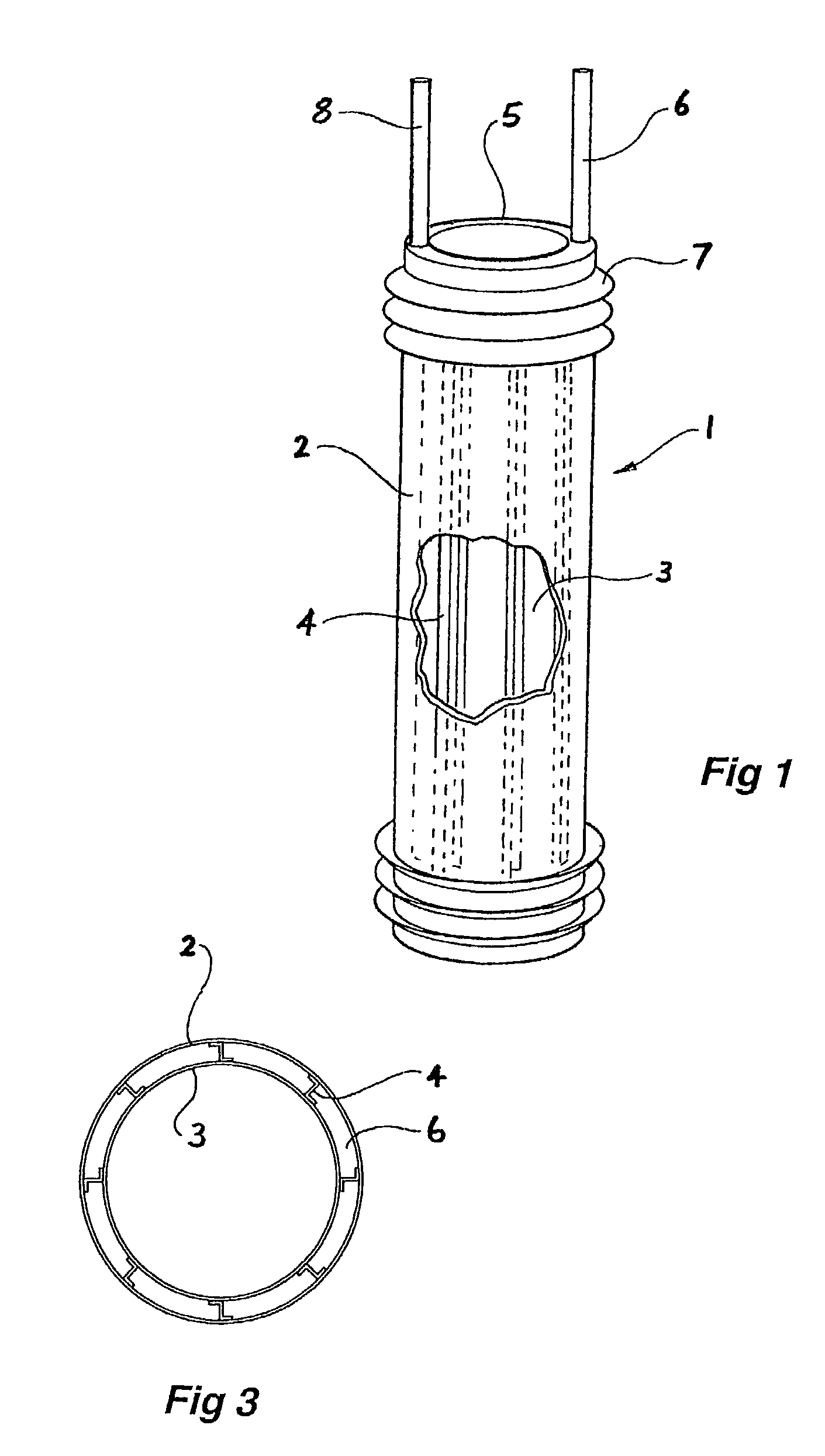
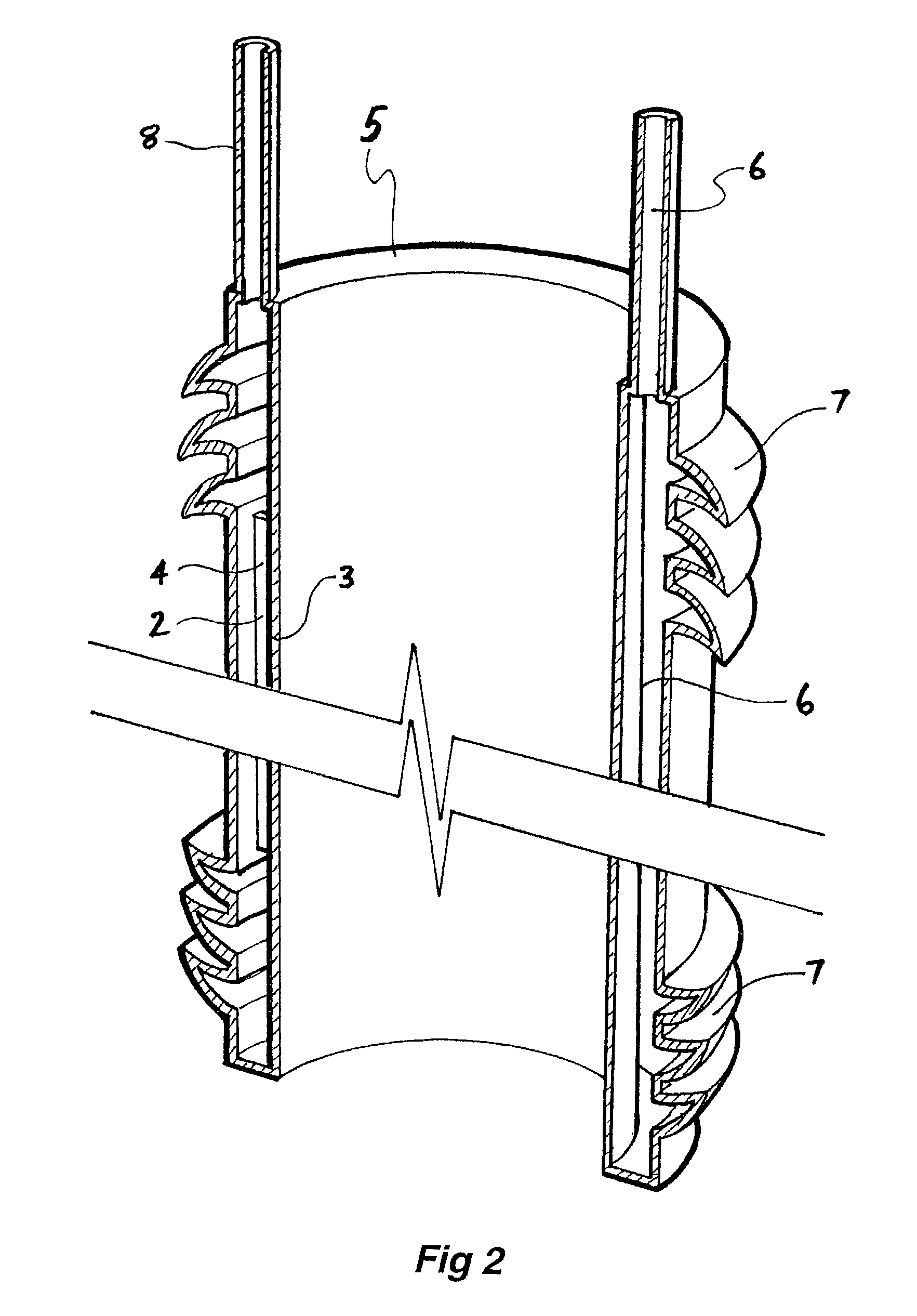
[0067]Now looking more closely at the drawings and, in particular, FIGS. 1 to 3 which show a first embodiment of the graft according to this invention, it will be seen that the graft comprises an annular tubular hollow body 1, which is formed from an outer wall 2 and an inner wall 3. Between the inner and outer walls are webs 4, which do not extend the full length of the graft. The annular hollow body has an end wall 5 between the inner wall 3 and the outer wall 2. The walls 2, 3 and 5 define a hollow space 6 into which can be inserted a settable or filler material under slight pressure to inflate the graft to a predetermined or selected tubular shape as shown in FIG. 1 and then after setting of the settable or filler material, the graft remains in that shape. The graft has an inflow tube 6 at one end through which can be supplied the settable or filler material. There is also a further return or outflow tube 8 for return of excess settable or filler material. The outflow tube 8 cou...


PUM


Abstract

A graft (1) which is in the form of an inflatable member adapted to be formed into a predetermined and/or selected shape when deployed in situ by filling with a filler material (6) which can be made rigid in situ and deployed on a balloon catheter (12). The deployment balloon (13) is formed from a non-compliant material.

Description

CROSS-REFERENCE TO RELATED APPLICATIONS[0001]This application claims priority of Australian Provisional Application Ser. No. PR 8472 filed Oct. 26, 2001.TECHNICAL FIELD[0002]This invention relates to a medical device and in particular to an endoluminal graft.BACKGROUND OF THE INVENTION[0003]Abdominal aortic aneurysms and problems in other body lumens have been treated by the use of stent grafts or prostheses of a variety of constructions, but due to their essentially rigid construction, even in a collapsed state, there are problems inserting such grafts into an aorta or other body lumen.SUMMARY OF THE INVENTION[0004]It is the object of this invention to provide a graft, which is of a minimal size for insertion, but can carry out essentially the same function as existing stent grafts.[0005]Also, when treating occlusive disease in arteries, it is desirable to have a delivery system, which is as small as possible during delivery, but can be expanded in situ to a selected size to treat ...

Claims


Application Information

Patent Timeline
IPC IPC(8): A61F2/06A61L31/00A61F2/02A61F2/07A61F2/30A61F2/848A61F2/945A61F2/954A61F2/958A61M25/00
CPCA61F2/07A61F2/954A61F2/958A61F2/848A61F2/945A61F2250/0003A61F2002/061A61F2002/067A61F2002/30583A61F2210/0085A61L27/58A61L27/14A61M25/10
Inventor LAWRENCE-BROWN, MICHAELLIFFMAN, KURTHARTLEY, DAVID ERNEST
Owner COOK MEDICAL TECH LLC
Why Eureka
Try Eureka