Article support rack

a technology for supporting racks and articles, applied in the field can solve the problems of low article storage efficiency of article support racks, and achieve the effects of reducing separation distance, improving article storage efficiency, and ensuring the structural strength of each shelf row

Active Publication Date: 2019-05-14
DAIFUKU CO LTD
View PDF20 Cites 4 Cited by
  • Summary
  • Abstract
  • Description
  • Claims
  • Application Information

AI Technical Summary

Benefits of technology

[0004]As such, provided to rack portions each of which can support a plurality of articles with the articles arranged along the horizontal direction in the article support rack shown in FIG. 5 of Patent Document 1 are vertical support frame members which are used to separate the storage sections (storage locations for articles) that are adjacent to each other along the horizontal direction. And each of these vertical support frame members is so arranged to extend from the back face toward the front face of the article support rack at a location between two articles that are horizontally adjacent to each other. And thus, in such an article support rack, the distance between any two supported articles which are horizontally adjacent to each other on a rack portion tends to be relatively large because of the presence of the vertical support frame member, which tends to lower the article storage efficiency of the article support rack.
[0005]To address this issue, an article support rack is desired for which the article storage efficiency is improved while properly maintaining article supporting strength of the rack portions.
[0007]With such an arrangement, since each shelf row includes rib portions in addition to one or more main body portions, each shelf row supported in a cantilever fashion by the shelf support members can be strengthened against bending moment applied to it, thus, allowing proper structural strength of each shelf row for supporting articles to be maintained.
[0008]And, with such an arrangement, each of such rib portions used to properly maintaining structural strength for supporting articles has a first portion so located to be higher than a lower level article which is an article supported by the lower level shelf row, and a second portion located lower than the first portion. And each second portion is so located that the second portion does not overlap with the maximum width areas of a lower level article as seen along the first direction. This allows for an arrangement in which neither the first portion nor the second portion of the rib portion is located in a space across which two maximum width areas (of two articles that are supported by a lower level shelf row and are adjacent to each other along the first direction) face each other along the first direction. As a result, it becomes possible to secure a distance between a lower level article and other surrounding objects and also to reduce the separation distance, along the first direction, between the two mutually-facing maximum width areas of two lower level articles that are adjacent to each other along the first direction, compared with a case in which a rib portion is located in such a space across which two maximum width areas face each other. And so, the article storage efficiency of the article support rack can be maintained at a high level.
[0009]Further, with the present arrangement described above, the second portion of each of the rib portions is so located that, as seen along the first direction, the second portion overlaps with at least one of (a) width decreasing areas and (b) any portion or portions that are located to the back-face side of the width decreasing areas, of the lower level article. This makes it easier to make the vertical dimension of the back-face side end portion of each rib portion sufficiently large for the corresponding shelf row to have proper strength for supporting articles, compared with a case in which the second portion is so located that no part of the second portion overlaps with the lower level article. Note that a portion of the second portion that overlaps with a lower level article is located in a space across which outer surfaces (of two lower level articles that are adjacent to each other along the first direction) are located from each other along the first direction. However, the separation distance, along the first direction, between the two width decreasing areas (and the portion or portions on a back-face side of the width decreasing areas) of two lower level articles that are adjacent each other along the first direction is greater than the separation distance between the two mutually-facing maximum width areas of such two lower level articles. Therefore, even when a second portion is located in such a space, the separation distance, along the first direction, between the two mutually-facing maximum width areas of two lower level articles that are adjacent to each other along the first direction can be kept small while properly securing the separation distance between any outer surface of a lower level article and a second portion.
[0010]As such, an article support rack is provided for which the article storage efficiency can be improved while properly maintaining article supporting strength of the rack portions.

Problems solved by technology

And thus, in such an article support rack, the distance between any two supported articles which are horizontally adjacent to each other on a rack portion tends to be relatively large because of the presence of the vertical support frame member, which tends to lower the article storage efficiency of the article support rack.

Method used


Image

  • Article support rack
  • Article support rack
  • Article support rack

Examples


Embodiment Construction

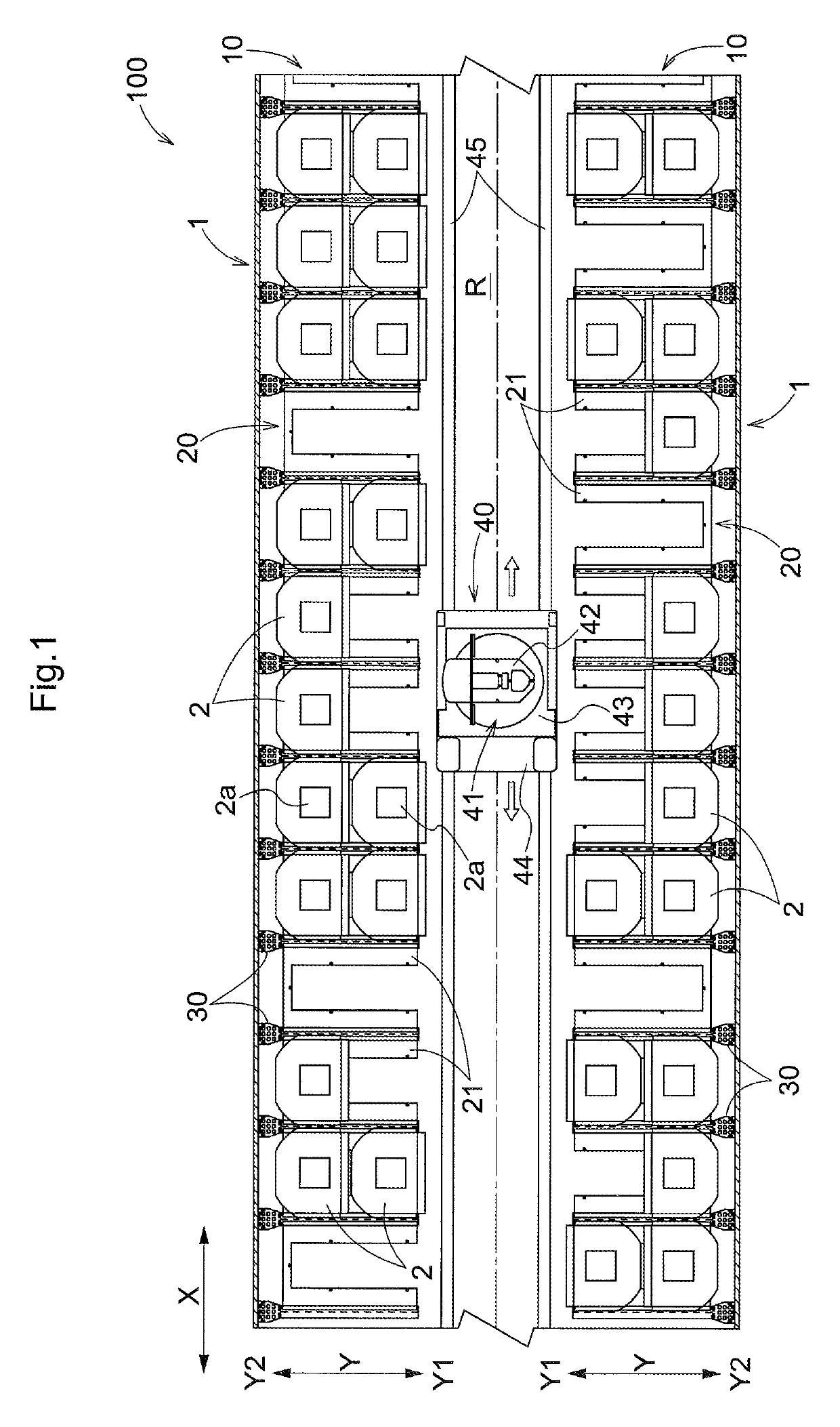
[0019]Embodiments of an article support rack are described next with reference to the attached drawings. In the present embodiment, an example is described in which an article support rack in accordance with the present disclosure is used in an article storage facility in which a transport device places articles in, and retrieves articles from, the article support rack.

[0020]As shown in FIG. 1, the article storage facility 100 includes article support racks 1 each having rack portions 10 each configured to support articles 2, and a transport device 40 configured to transport articles 2, one at a time, to or from any of the rack portions 10. Each rack portion (a portion of a rack) 10 is configured to support a plurality of articles 2 with the articles 2 arranged one adjacent to another along a first direction X parallel to a horizontal plane. In the present embodiment, each rack portion 10 is further configured to support a plurality of articles 2 (two articles 2 in the present examp...


PUM


Abstract

An article support rack is disclosed having a plurality of rack portions. Each shelf row includes one or more main body portions and rib portions, and is supported by shelf support members in a cantilever fashion from a back-face side. Each of the rib portions is located, in plan view, between two articles that are adjacent to each other along a first direction and that are supported by a lower level shelf row which is one of the shelf rows that is located one level below a shelf row to which the rib portion is provided. Each of the rib portions has a first portion located higher than lower level articles each of which is an article supported by the lower level shelf row, and a second portion located lower than the first portion. Each second portion is so located that the second portion does not overlap with the maximum width areas of a lower level article as seen along the first direction.

Description

CROSS-REFERENCE TO RELATED APPLICATION[0001]This application claims priority to Japanese Patent Application No. 2017-129062 filed Jun. 30, 2017, the disclosure of which is hereby incorporated in its entirety by reference.FIELD OF THE INVENTION[0002]The present invention relates to an article support rack having a plurality of levels of rack portions so that the rack portions are arranged one rack portion over another along a vertical direction, each rack portion being capable of supporting a plurality of articles with the articles arranged one adjacent to another along a first direction parallel to a horizontal plane.BACKGROUND[0003]An example of article support racks such as one described above is disclosed in JP Publication of Application No. 2002-252277 (Patent Document 1). FIG. 5 of Patent Document 1 shows a storage rack (50) comprising a plurality of storage sections (55) each for storing a semiconductor wafer carrier with the storage sections (55) located next to each other al...

Claims


Application Information

Patent Timeline
Patent Type & Authority Patents(United States)
IPC IPC(8): B65G1/02A47B57/56H01L21/677B65G1/04
CPCB65G1/02H01L21/67769A47B57/56B65G1/0407
Inventor YOSHIMOTO, TADAHIROYOSHIOKA, HIDEOABE, TAKESHI
Owner DAIFUKU CO LTD
Why Eureka
Try Eureka