
Air bag device

a technology of air bags and air bags, which is applied in the direction of pedestrian/occupant safety arrangements, vehicular safety arrangments, vehicle components, etc., can solve the problems of difficult to reliably avoid the early interference of air bags, the direction of air bags expansion is not stabilized, and the occupants are difficult to restrain softly

Inactive Publication Date: 2002-11-05
HONDA MOTOR CO LTD
View PDF15 Cites 64 Cited by
  • Summary
  • Abstract
  • Description
  • Claims
  • Application Information

AI Technical Summary

Benefits of technology

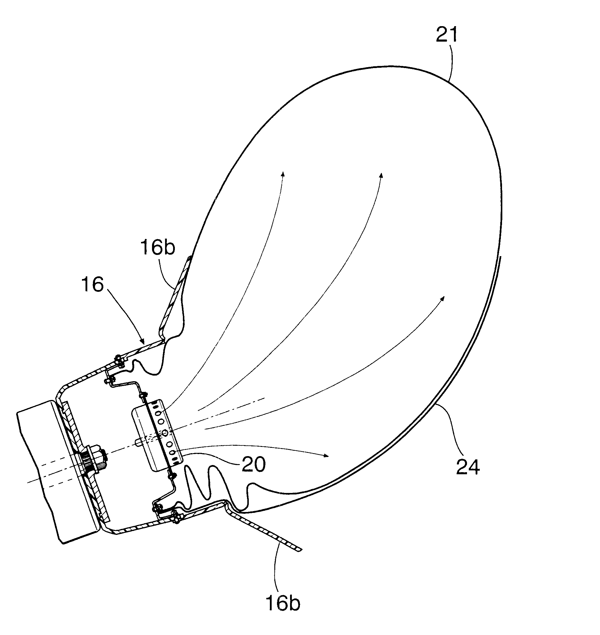
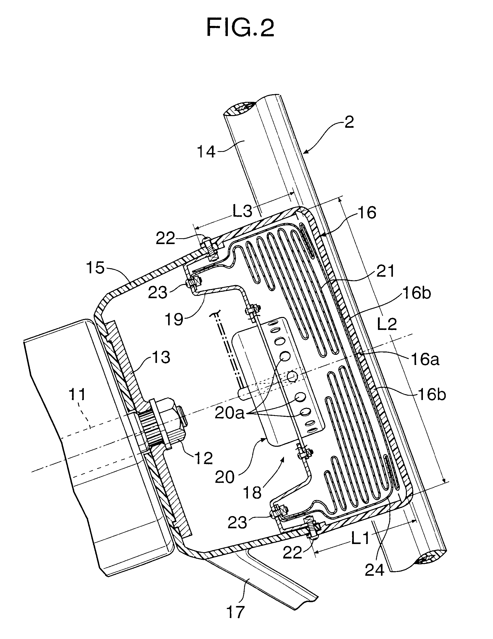
With the above arrangement, the folded-up air bag is covered from the rear side of the vehicle to the front side of the vehicle by the deployment-limiting sheet disposed between the folded-up air bag and the inner surface of the module cover. Therefore, the air bag deployed at the initial stage can be inhibited from being expanded rearwards of the vehicle by the deployment-limiting sheet, thereby reliably avoiding the early interference of the air bag with an occupant. Particularly, the deployment-limiting sheet is longer than the length of the inner periphery of the module cover in the longitudinal direction of the vehicle body and hence, it is possible to reliably inhibit the air bag at the initial state of the deployment from being expanded rearwards of the vehicle body.
With the above arrangement, the folded-up air bag is covered from the rear side of the vehicle to the front side of the vehicle by the deployment-limiting sheet disposed between the folded-up air bag and the inner surface of the lid. Therefore, the air bag deployed at the initial stage can be inhibited from being expanded rearwards of the vehicle by the deployment-limiting sheet, thereby reliably avoiding the early interference of the air bag with an occupant. Particularly, the deployment-limiting sheet is longer than the length of the arc of the circle which has its center immediately above the first reference point at the rear end of the lid, passes through the first reference point, and which is tangent at the second reference pointy to the front glass, the arc extending on the rear side of the vehicle body between the first and second reference points. Therefore, it is possible to reliably inhibit the air bag at the initial stage of the deployment from being expanded rearwards of the vehicle body.

Problems solved by technology

In addition, the air bag breaks a fragile portion of a lid in the course of the expansion to deploy into the vehicle compartment, and for this reason the air bag may expand suddenly into the vehicle compartment the moment it breaks the lid, in some cases.
Therefore, when the distance between an occupant and the air bag device is small, the following problem may be encountered: the air bag expanded at a high speed at the initial stage of the deployment may interfere with the occupant, thereby making it difficult to restrain the occupant softly.
In the above conventional method, however, the direction of expansion of the air bag is not stabilized due to delicate differences in precisely how the air bag is folded, and it is difficult to reliably avoid the early interference of the air bag with the occupant.

Method used


Image

  • Air bag device
  • Air bag device
  • Air bag device

Examples


Embodiment Construction

The mode for carrying out the present invention will now be described by way of embodiments of the present invention shown in the accompanying drawings.

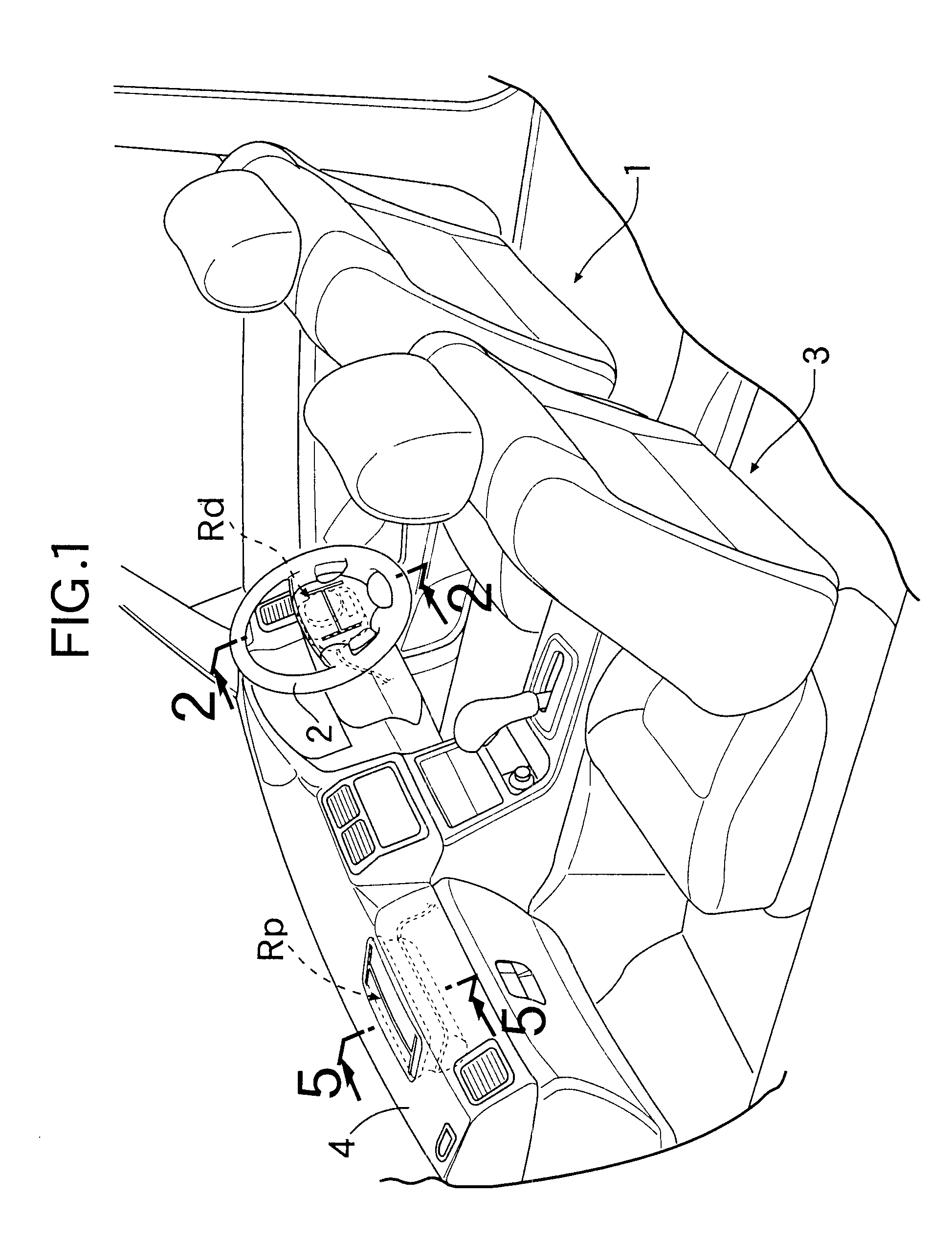
FIGS. 1 to 9 show a first embodiment, of the present invention, including two air bag devices which are respectively associated with a driver's seat and a front passenger's seat of a vehicle. FIG. 1 is a perspective view of a front portion of an occupant compartment in an automobile; FIG. 2 is an enlarged sectional view taken along a line 2--2 in FIG. 1; FIG. 3 is an exploded perspective view of an air bag device for a driver's seat; FIG. 4 is a view for explaining the operation at an initial stage of the deployment of the air bag device for the driver's seat; FIG. 5 is an enlarged sectional view of an air bag device for a front passenger's seat taken along a line 5--5 in FIG. 1; FIG. 6 is an enlarged view of an essential portion of the air bag device shown in FIG. 5; FIG. 7 is a sectional view taken along a line 7--7 in FIG. 6; FIG....


PUM


Abstract

A folded-up air bag is accommodated in a module cover of a steering wheel, and a peripheral edge of an opening in the air bag is fixed to a retainer supporting an inflator. The folded-up air bag is covered from a rear side of a vehicle to a front side of the vehicle by a deployment-limiting sheet disposed along an inner surface of the module cover and fixed at one end thereof to the retainer. The deployment-limiting sheet is longer than a length of an inner periphery of the module cover in a longitudinal direction of the vehicle body. Thus, it is possible to inhibit the air bag from being expanded rearwards of the vehicle body at an initial stage of deployment by the deployment-limiting sheet, thereby avoiding the early interference with an occupant.

Description

1. Technical Field to which the Invention BelongsThe present invention relates to an air bag device designed so that an air bag thereof is deployed into an occupant compartment of a vehicle by a gas generated by an inflator upon collision of the vehicle to restrain an occupant.2. Description of Related ArtWhen an air bag is deployed into a vehicle compartment by a gas generated by an inflator upon collision of a vehicle, the air bag having a smaller volume at an initial stage of the deployment is expanded quickly, while the air bag having larger volume at a late stage of the deployment is expanded slowly. In addition, the air bag breaks a fragile portion of a lid in the course of the expansion to deploy into the vehicle compartment, and for this reason the air bag may expand suddenly into the vehicle compartment the moment it breaks the lid, in some cases.Therefore, when the distance between an occupant and the air bag device is small, the following problem may be encountered: the a...

Claims


Application Information

Patent Timeline
IPC IPC(8): B60R21/20B60R21/16B60R21/203B60R21/205B60R21/217
CPCB60R21/203B60R21/205B60R21/2171B60R2021/161
Inventor HIGUCHI, HITOSHIOTSUKA, TAKERUKAMIJI, KOICHIKAWAMURA, NOBUYUKISATO, MASAESAITO, KENICHI
Owner HONDA MOTOR CO LTD
Learn More