Multiple part manual dispensing syringe

a syringe and manual technology, applied in the field of multi-part dispensing syringes, can solve the problems of not only messy operation, but also waste, and the removal of tape is not only complicated, so as to achieve the effect of reducing waste, reducing waste, and reducing was

Inactive Publication Date: 2002-12-03
PRC DE SOTO INT INC
View PDF12 Cites 114 Cited by
  • Summary
  • Abstract
  • Description
  • Claims
  • Application Information

AI Technical Summary

Benefits of technology

A cylindrical barrier is threadably detachable secured to the dasher on its axial ends facing the plunger. Consequently, with the dasher and barrier positioned together, the dasher and barrier sealingly engages the inner periphery of the tube chamber and divides the tube chamber i

Problems solved by technology

This previous design, however, is disadvantageous since it may leave portions of the foil barrier floating within the mixed material.
The disadvantage of this type of previously know dispenser is at the removal the tape is not only complicated, but also contributes waste.
Furthermore, the previously known dispensers of this type require a tight seal between the dasher and the interior of the tube which in turn requires a high mixing force to be applied to the dasher rod to axially displace the das

Method used


Image

  • Multiple part manual dispensing syringe
  • Multiple part manual dispensing syringe
  • Multiple part manual dispensing syringe

Examples


Embodiment Construction

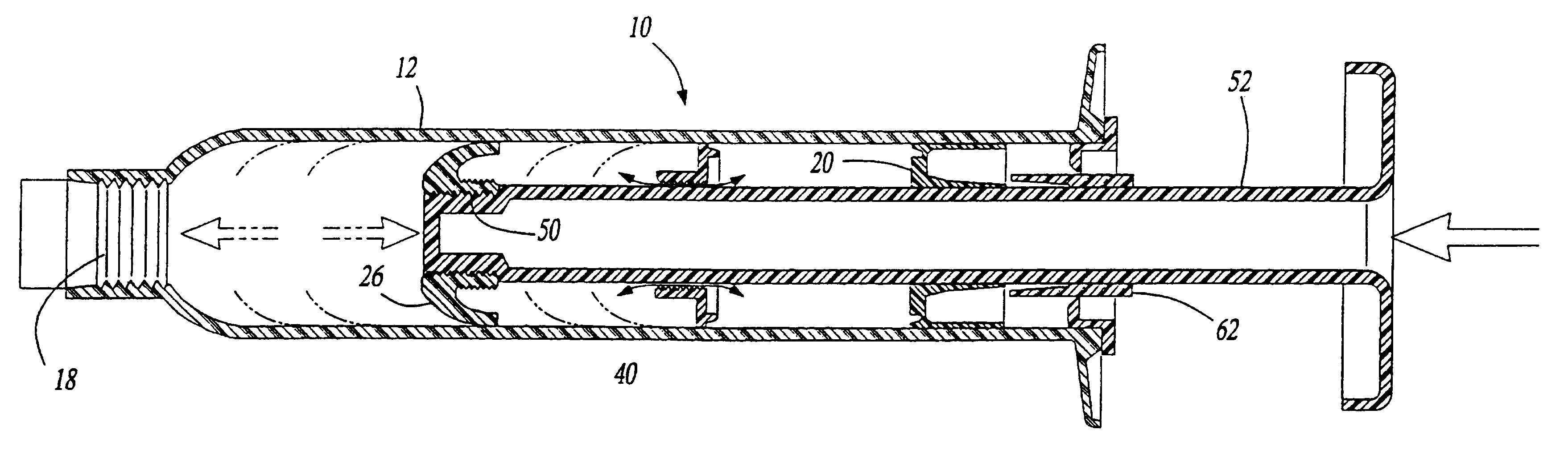
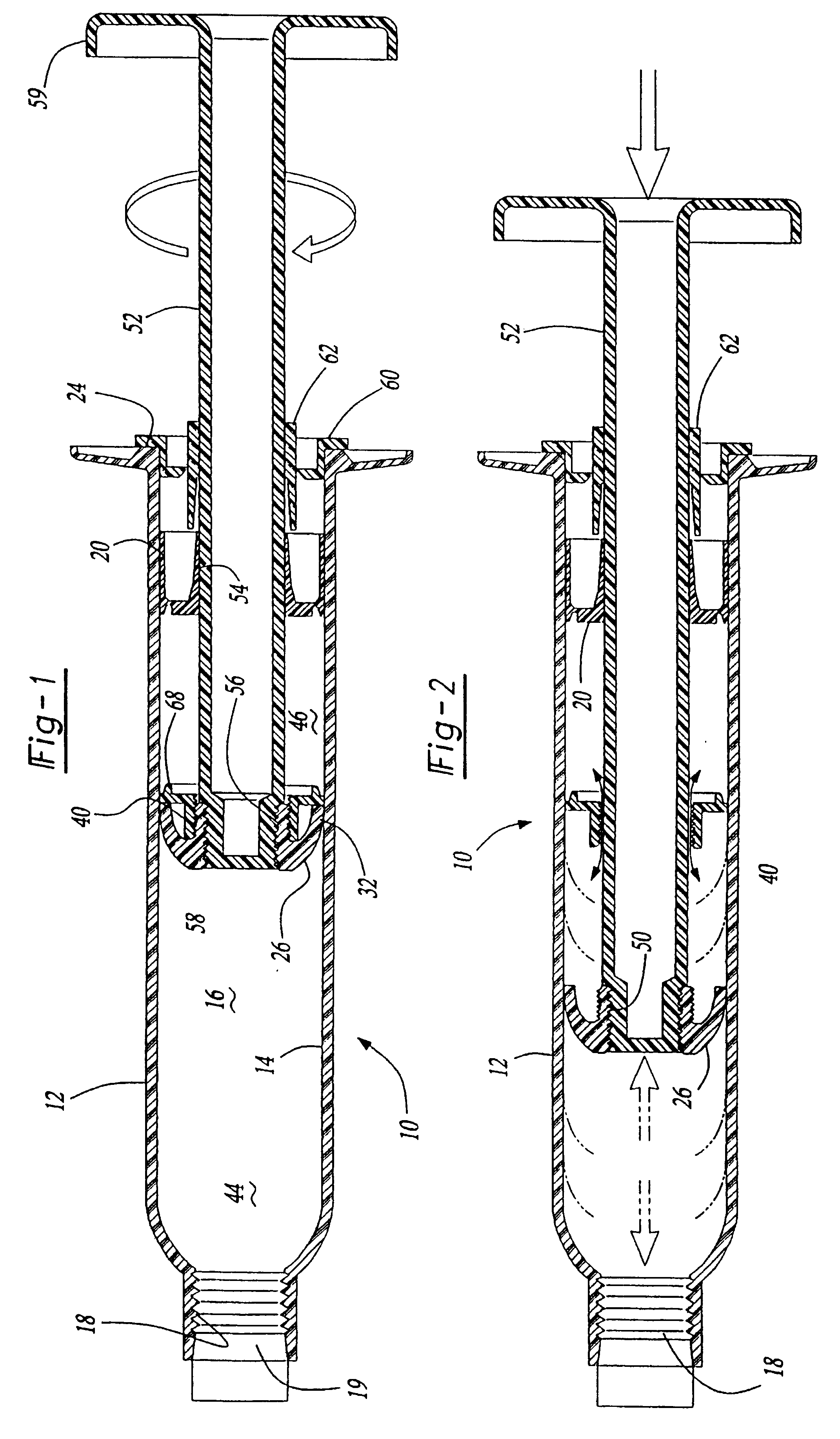
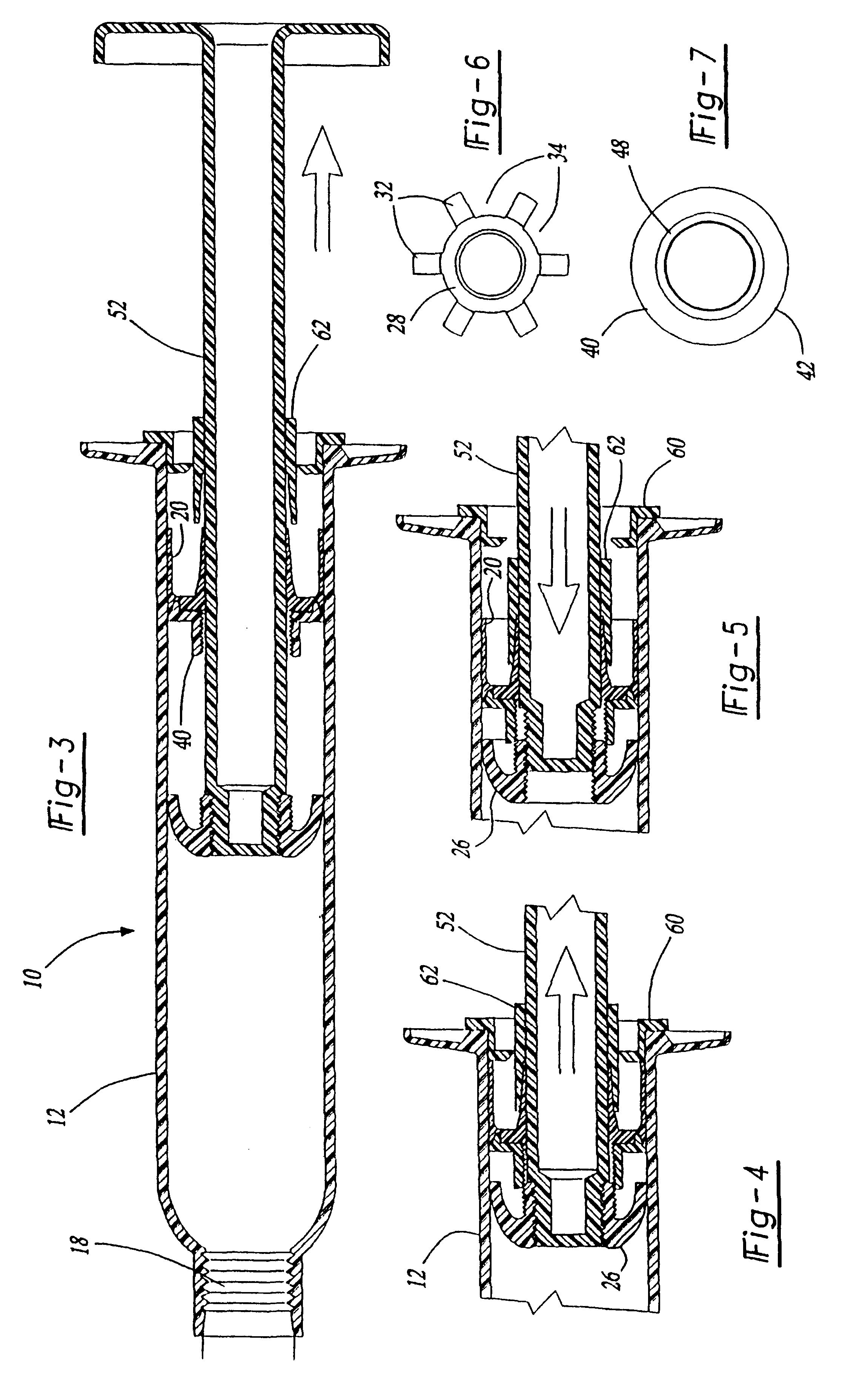
With reference first to FIGS. 1 and 8 of the drawing, a preferred embodiment of the two-part dispenser 10 of the present invention is there shown and comprises an elongated cylindrical tube 12. The interior walls 14 of the tube define an elongated cylindrical chamber 16 having a dispensing opening 18 at one end. Preferably, the opening 18 is internally pipe threaded as shown at 19 to receive a complementary externally threaded dispensing tip.

A cylindrical plunger 20 is longitudinally slidably mounted within the tube chamber 16 and such that its outer periphery sealingly engages the inner wall 14 of the tube 12. In its initial position shown in FIG. 1, i.e., prior to dispensing of the material contained within the tube chamber 16, the plunger 20 is positioned at an end 24 of the tube 12 opposite from the dispensing opening 18.

With reference now to FIGS. 1, 8 and 6, a cylindrical dasher 26 is positioned at an intermediate point in the housing chamber 16 between the plunger 20 and disp...


PUM


Abstract

A syringe (10) includes a tube (12) defining a chamber (16) with a dispensing opening (18). A plunger (20) is slidably mounted in the tube and is initially positioned at the end (24) of the chamber opposite the dispensing opening. A dasher (26) having an opening (34) is positioned within the chamber at an intermediate point. A cylindrical barrier (40) is detachably secured to the dasher (26). Thus, with the barrier secured to the dasher, the barrier and dasher sealingly engages the tube dividing it into two subchambers (44, 46). An elongated rod (52) extends through openings (54, 56) in the plunger and the barrier and is secured to the dasher. Rotation of the rod detaches the barrier from the dasher establishing communication between the subchambers. A locking sleeve (62) frictionally secures the rod and the plunger together when the rod is moved to a retracted position (FIG. 4). Furthermore, optionally the rod is hollow (FIG. 9) and defines a third subchamber (80) containing a third liquid.

Description

I. Field of the InventionThe present invention relates to a multiple-part dispensing syringe.II. Description of the Prior ArtThere are many previously known dispensing syringes for dispensing epoxy, polyurethane and other multi-part solutions.These previously known syringes typically comprise an elongated tube which defines an elongated cylindrical chamber. A dispensing opening is formed at one end of the chamber while an axially slidably mounted plunger is initially positioned at the opposite end of the tube chamber.A dasher is conventionally positioned within the tube chamber at a point intermediate the plunger and the dispensing opening. An elongated rod then extends through the dispensing opening and is detachably secured to the dasher. The dasher itself contains a plurality of axial openings formed through it and the rod is used to axially displace the dasher within the interior tube chamber in order to intermix the contents of the tube chamber.These previously known multi-part...

Claims


Application Information

Patent Timeline
IPC IPC(8): A61M5/315B65D83/00A61M5/28A61M5/31B65D81/32B65D85/00
CPCA61M5/31596B65D83/0005A61M5/286A61M2005/3128A61M2005/31598B67D7/74
Inventor MORRIS, DAVID PAULDANG, NGUYEN THAI
Owner PRC DE SOTO INT INC
Why Eureka
Try Eureka