Ultra-rugged, high-performance computer system

a computer system and ultra-rugged technology, applied in the direction of casings/cabinets/drawers, casings/cabinets/drawers, instruments, etc., can solve the problems of heat dissipation from a compact, rugged, and packag

Inactive Publication Date: 2003-01-07
IV PHOENIX GROUP
View PDF9 Cites 150 Cited by
  • Summary
  • Abstract
  • Description
  • Claims
  • Application Information

AI Technical Summary

Problems solved by technology

At the same time heat dissipation from a compact, rugged, package is a problem fo

Method used


Image

  • Ultra-rugged, high-performance computer system
  • Ultra-rugged, high-performance computer system
  • Ultra-rugged, high-performance computer system

Examples


Embodiment Construction

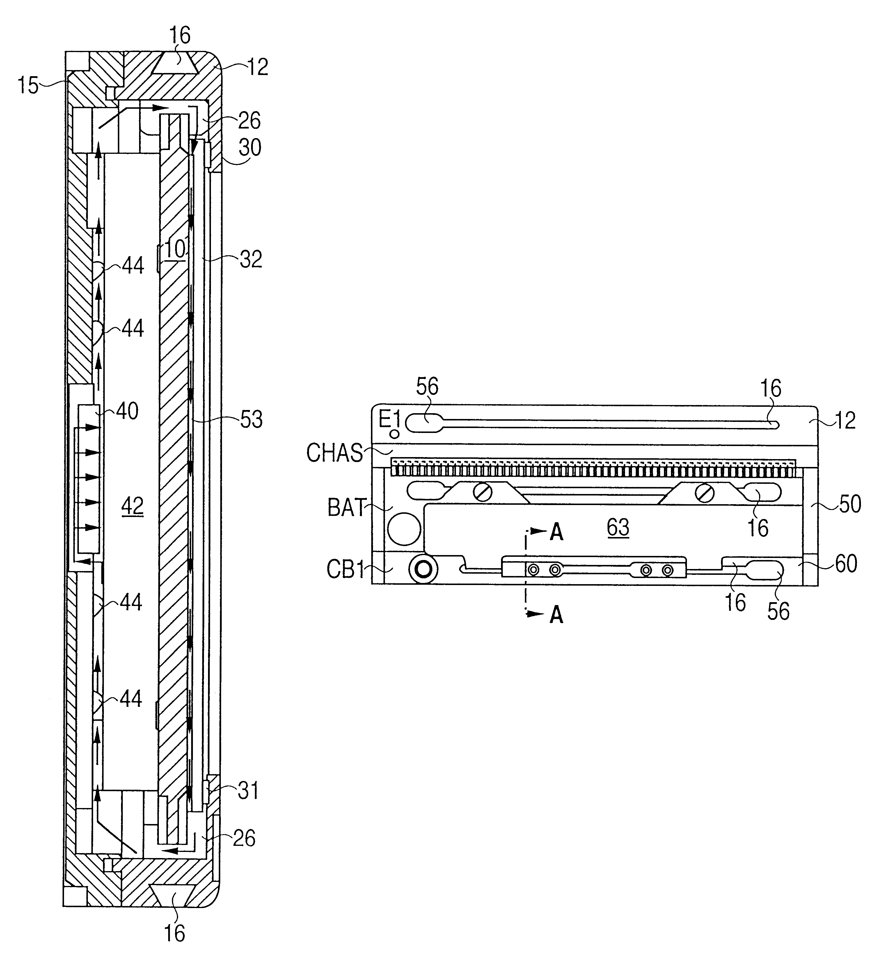
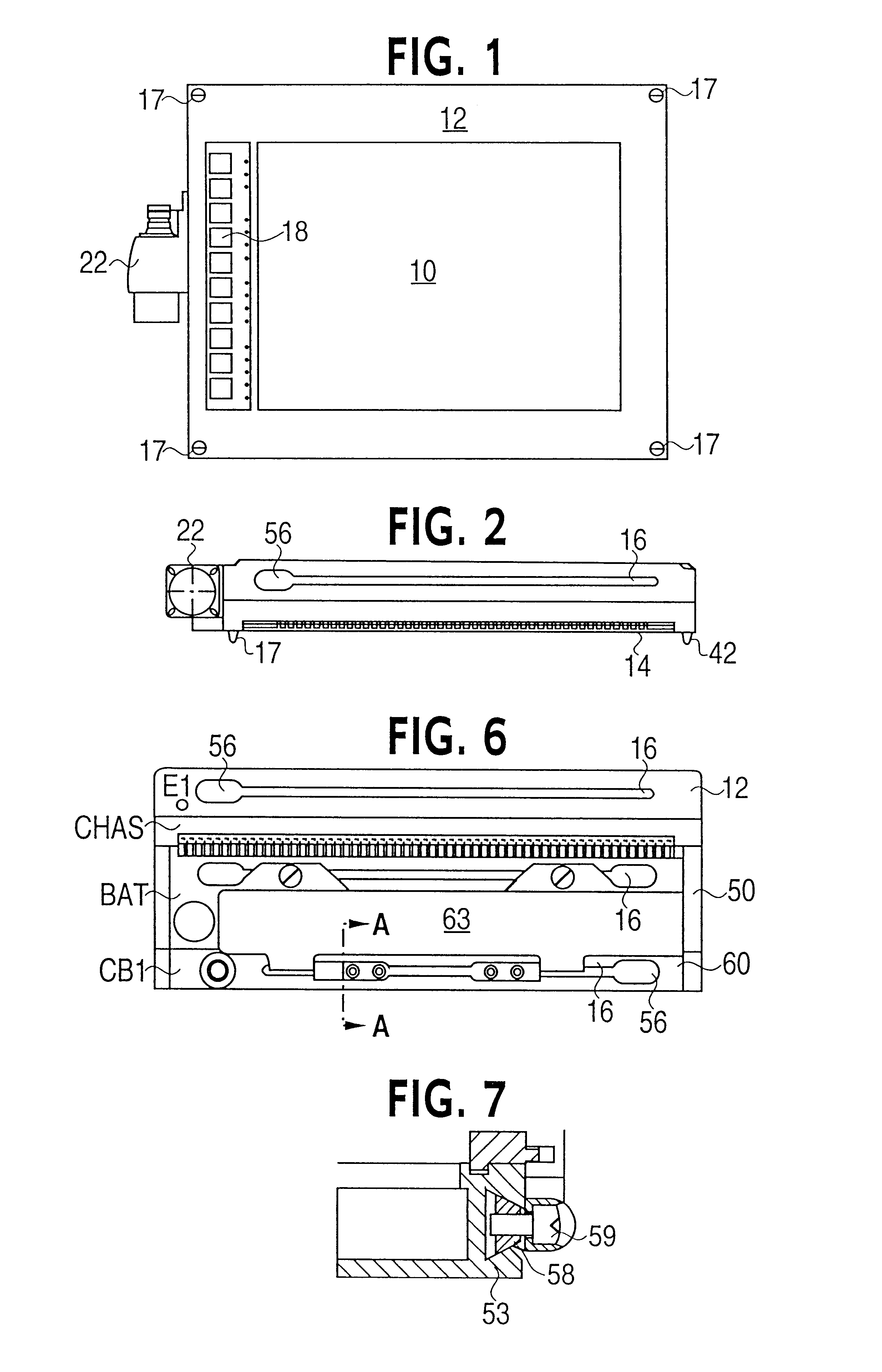
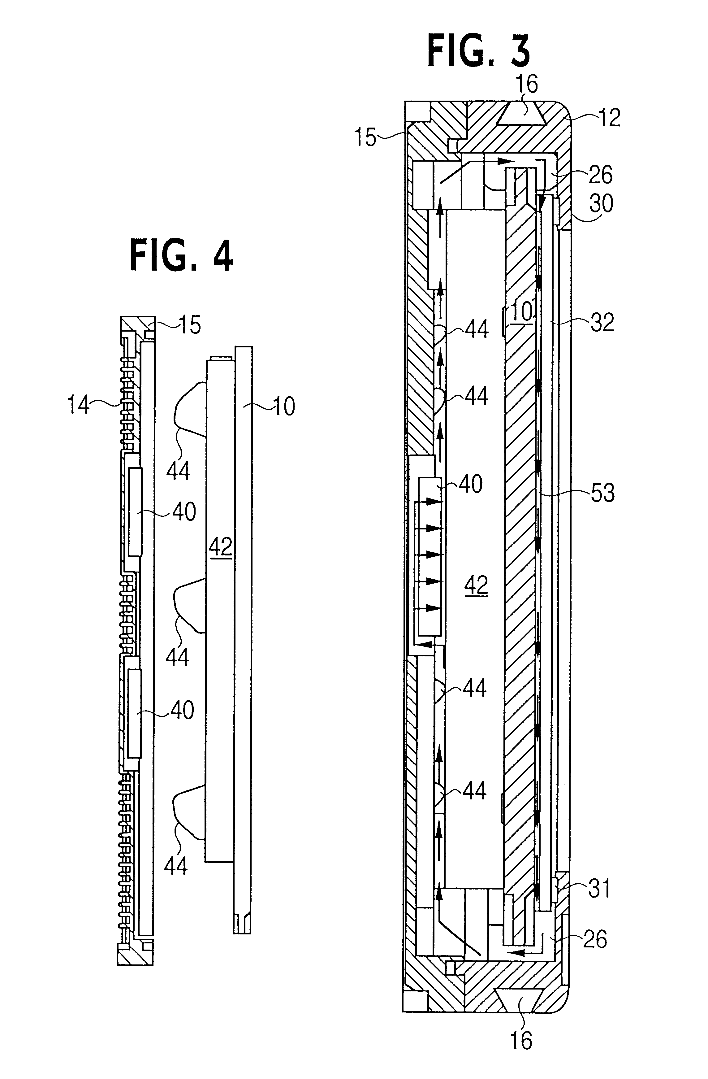
Refering now to FIGS. 1, 2, 3 and 4, the display module has a flat panel display screen 10, which is shock mounted in a rugged, two piece metal housing comprised of a front piece 12 and a rear piece 15. The housing has cooling fins 14 (not shown in FIG. 3) extending from the rear piece 15, opposite the display surface. There is a mounting bar 16 along each side (i.e. top, bottom, right and left) of the housing. This mounting bar 16 allows the display to be attached, separately from the other system components. This universal mounting capability can be used to attach the unit to a platform member and since there is a mounting bar on each side the mounted display can be orientated as desired. Four spring loaded, captive screws 17 are used to secure the display module to the processor module when the modules are stacked together.

The housing includes a key pad assembly 18 comprised, in this example, of ten key switches aligned in a vertical row with respect to the display screen 10. Thi...


PUM


Abstract

A display module includes a sealed, heat conductive housing, a display screen secured to the housing by spaced, resilient mounting members, a touch responsive screen separated from the display screen by a narrow air gap, an airtight seal between a peripheral lip of the housing and the touch responsive screen, and a fan in the housing to circulate a fluid through the gap.

Description

1. Field of the InventionThis invention relates to an ultra-rugged, high-performance, computer system comprised of modules that can be joined together into a unitary stack or mounted separately apart and, more particularly, to such a system with a high intensity display that can be read in direct sunlight.2. Description of the Prior ArtIn many severe operating environments, there is a need for a rugged, compact, but powerful computer system with a display that it can be viewed in direct sunlight. Oil rig platforms, wheeled and tracked military vehicles, ships, and aircraft are just some examples of these environments. It will be appreciated that in many of these environments, it is highly desirable to have the utmost flexibility and convenience in securing the system to an external structure. At the same time heat dissipation from a compact, rugged, package is a problem for a high performance system that includes a display with high luminous intensity.An object of this invention is ...

Claims


Application Information

Patent Timeline
IPC IPC(8): G02F1/133G02F1/13G06F1/16G06F1/20
CPCG02F1/13338G02F1/133382G06F1/1601G06F1/20G06F1/16G02F1/133385G06F2200/1631G06F2200/1612
Inventor PANDOLFI, RICHARDEDMAN, JOSEPH
Owner IV PHOENIX GROUP
Why Eureka
Try Eureka