Kit for a bus bar system for connecting bus bars with connectors of an electric installation device

Inactive Publication Date: 2003-01-14
RITTALWERK RUDOLF LOH GMBH & CO KG
View PDF6 Cites 16 Cited by
  • Summary
  • Abstract
  • Description
  • Claims
  • Application Information

AI Technical Summary

Problems solved by technology

Further problems arise when it is necessary to transmit particularly high currents via the connections.
This requires large cross sections of the connecting rails, which often can only be matched to the installation situation at the site after the bus bars and the installation devices are installed.

Method used


Image

  • Kit for a bus bar system for connecting bus bars with connectors of an electric installation device
  • Kit for a bus bar system for connecting bus bars with connectors of an electric installation device
  • Kit for a bus bar system for connecting bus bars with connectors of an electric installation device

Examples


Embodiment Construction

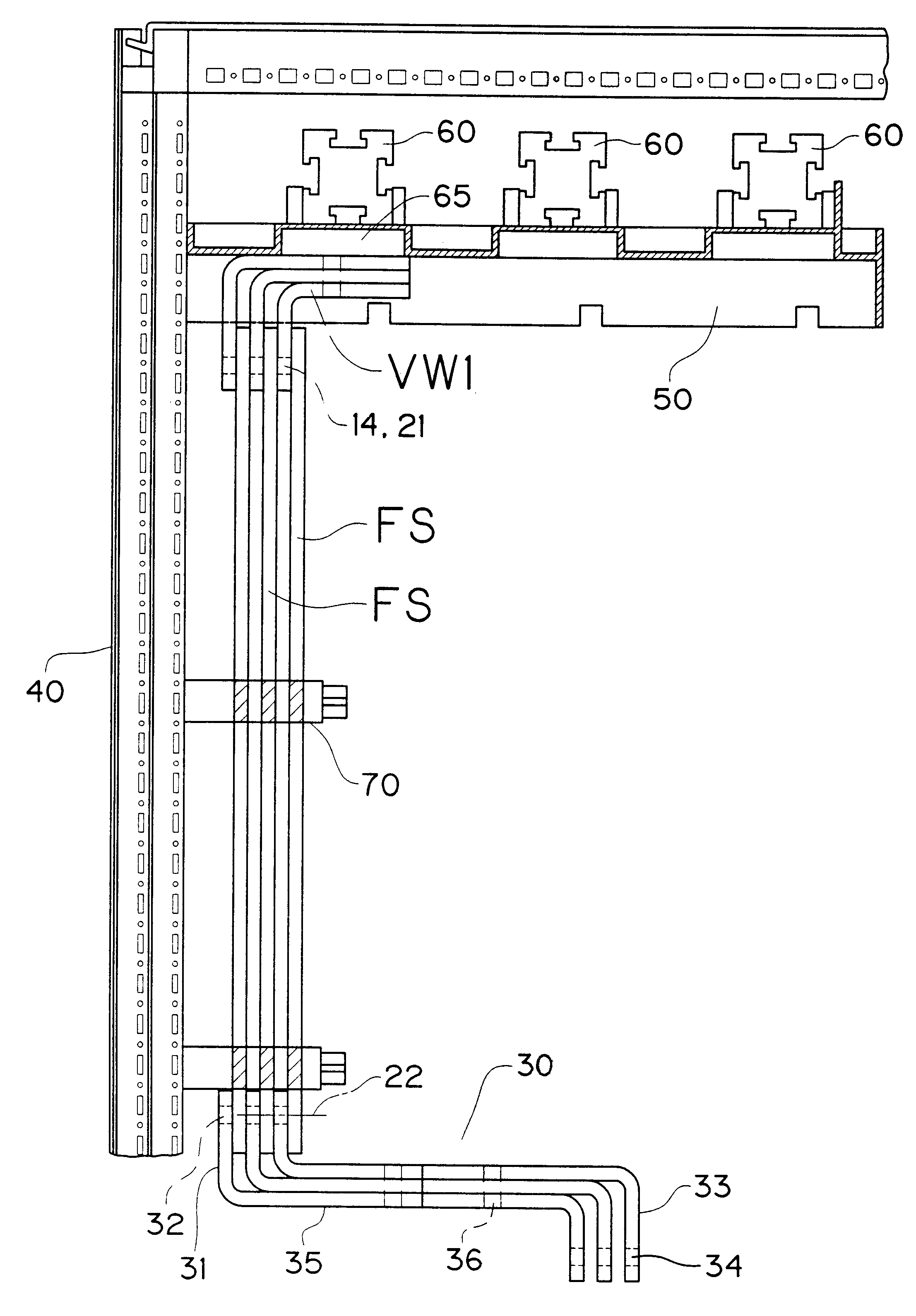
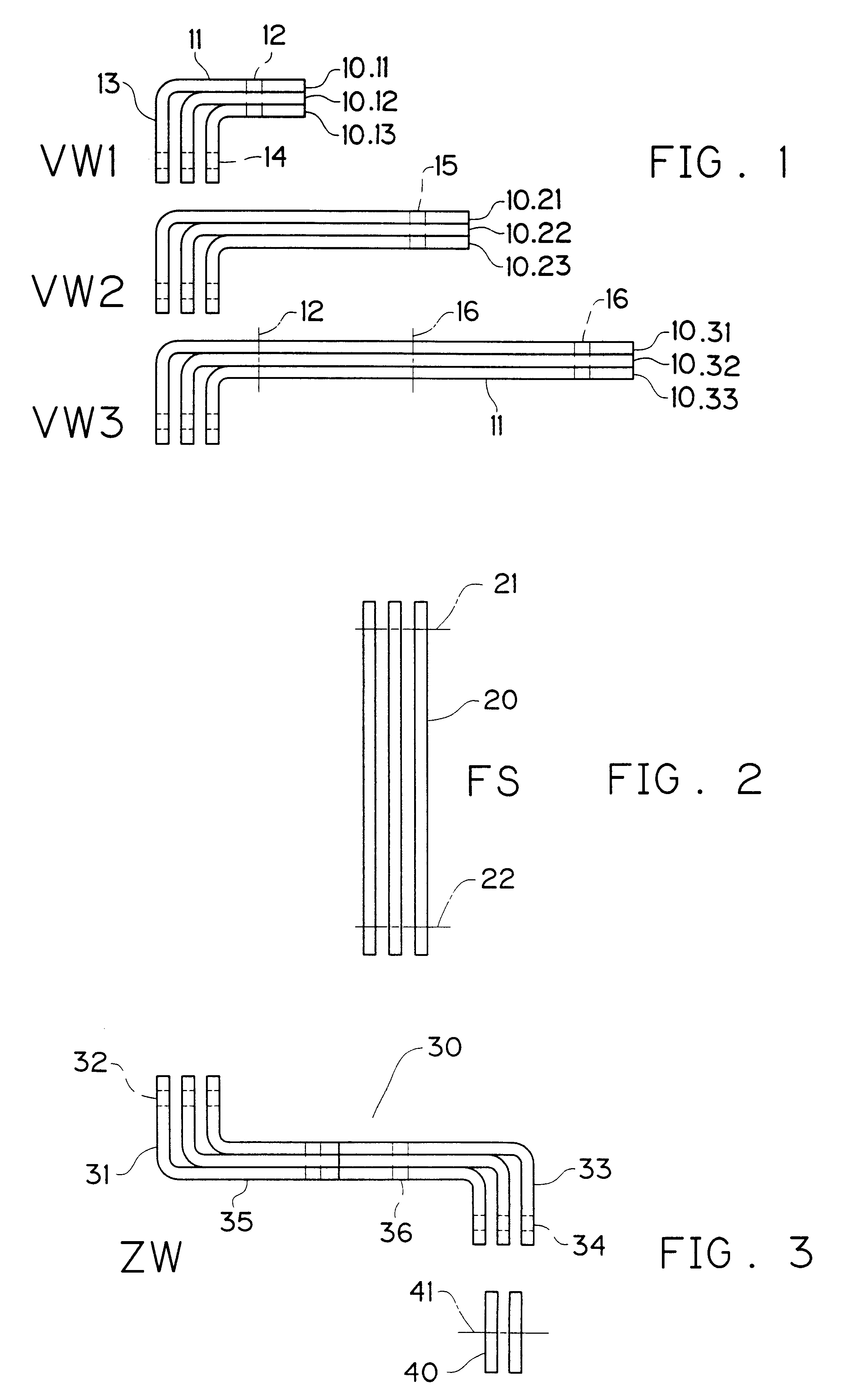
As FIGS. 1 to 3 show, all connecting elements are made of a flat material of a uniform cross section. Depending on the maximum current strength to be transmitted, a more or less large number of individual parts can be used. This invention will be explained in view of respectively three combined individual elements, which are called individual element sets.

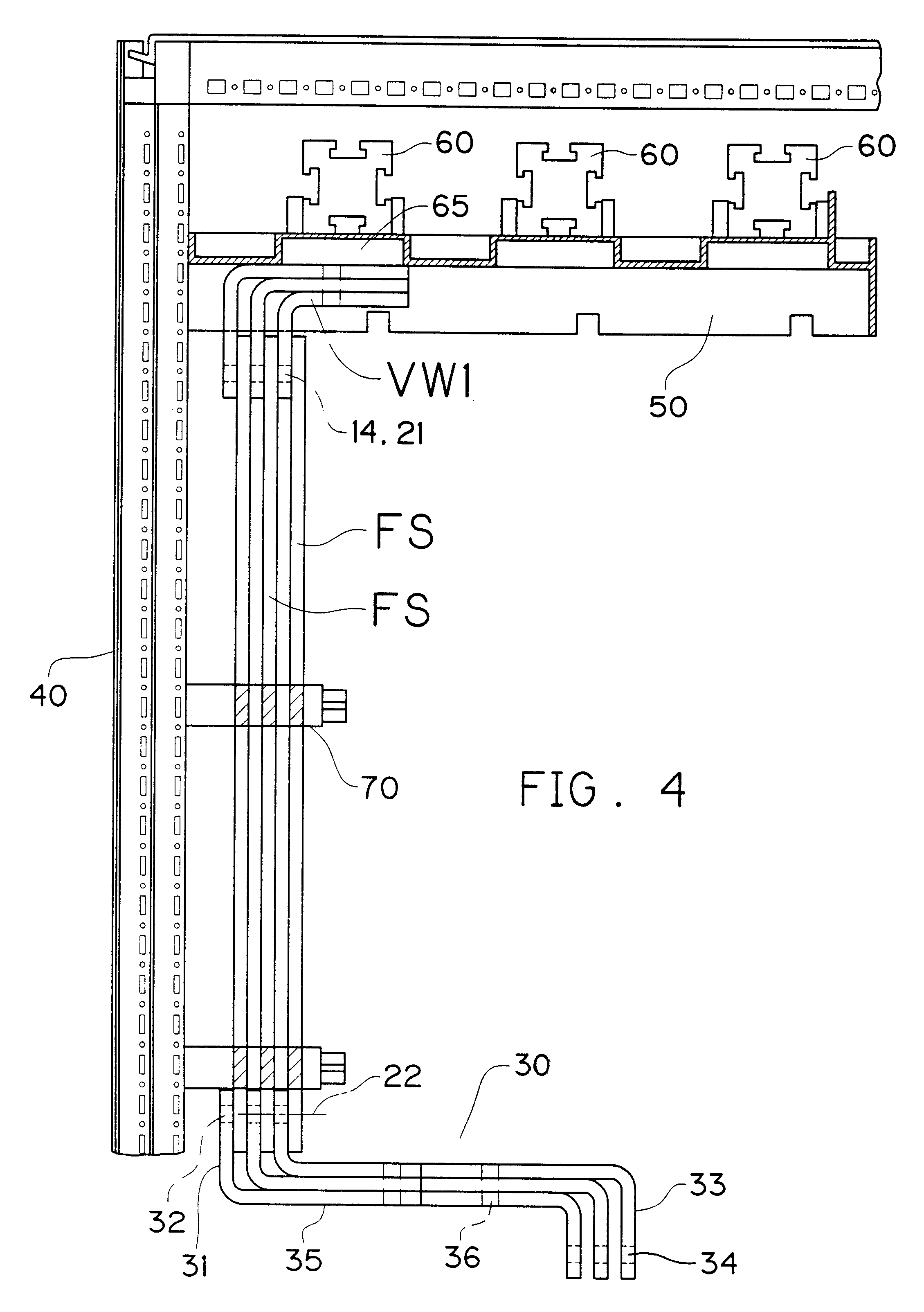
If, as shown in FIG. 4, three bus bars 60 of a rotary current bus bar system are arranged in a rack 40 in one horizontal plane, the connecting elbow sets VW1, VW2 and VW3, represented in FIG. 1, can be used for connecting the associated bus bar 60. Here, and as shown in FIG. 4, the connecting legs 11 of the connecting elbows 10.11, 10.12 and 10.13 are so long that they can be connected via the fastening bores 12 with the left bus bar 60. With the connecting elbow set VW2, the connecting legs 11 of the connecting elbows 10.21, 10.22 and 10.23 are so long, that they can be connected via their fastening bores 15 with the center bus ba...


PUM


Abstract

A kit for a bus bar system for connecting bus bars with connectors of an electric installation device, which avoids the production of special connecting rails, depending on the position of the connecting planes of the bus bars and the connectors of the installation device.

Description

1. Field of the InventionThis invention relates to a kit for a bus bar system for connecting bus bars with the connectors of an electric installation device.2. Description of Related ArtIn the field of switchgear cabinet production, connecting rails, which are bent from a flat material and / or beveled and which must be particularly matched to the installation locations of these elements, are used for connecting bus bars of the bus bar system with the connectors of the installation device. To worsen matters, the bus bars and the connectors of the installation device are arranged in planes which extend perpendicular with respect to each other and, depending on the installation possibilities in the switchgear cabinet, their planes can be differently offset horizontally and vertically with respect to each other. Further problems arise when it is necessary to transmit particularly high currents via the connections. This requires large cross sections of the connecting rails, which often ca...

Claims


Application Information

Patent Timeline
Patent Type & Authority Patents(United States)
IPC IPC(8): H02G5/00
CPCH02G5/00H02G5/005
Inventor WAGENER, HANS
Owner RITTALWERK RUDOLF LOH GMBH & CO KG
Why Eureka
Try Eureka