Method of and devices for fluorescence diagnosis of tissue, particularly by endoscopy

a tissue and fluorescence imaging technology, applied in the field of tissue fluorescence diagnosis, particularly by endoscopy, can solve the problems of reproducibility of this form of administration, comparatively low contrast image, and the most frequently occurring cause of death of lung cancer

a tissue and fluorescence imaging technology, applied in the field of tissue fluorescence diagnosis, particularly by endoscopy, can solve the problems of reproducibility of this form of administration, comparatively low contrast image, and the most frequently occurring cause of death of lung cancer

US6510338B1Inactive Publication Date: 2003-01-21KARL STORZ GMBH & CO KG

Image

  • Method of and devices for fluorescence diagnosis of tissue, particularly by endoscopy
  • Method of and devices for fluorescence diagnosis of tissue, particularly by endoscopy

Examples


Embodiment Construction

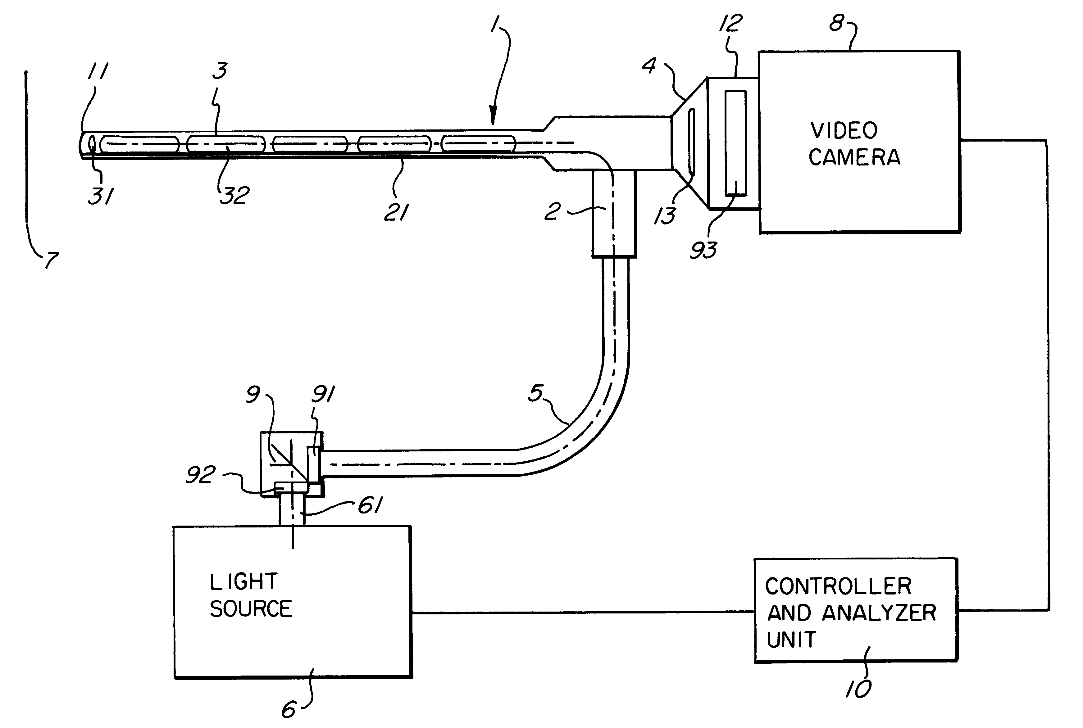
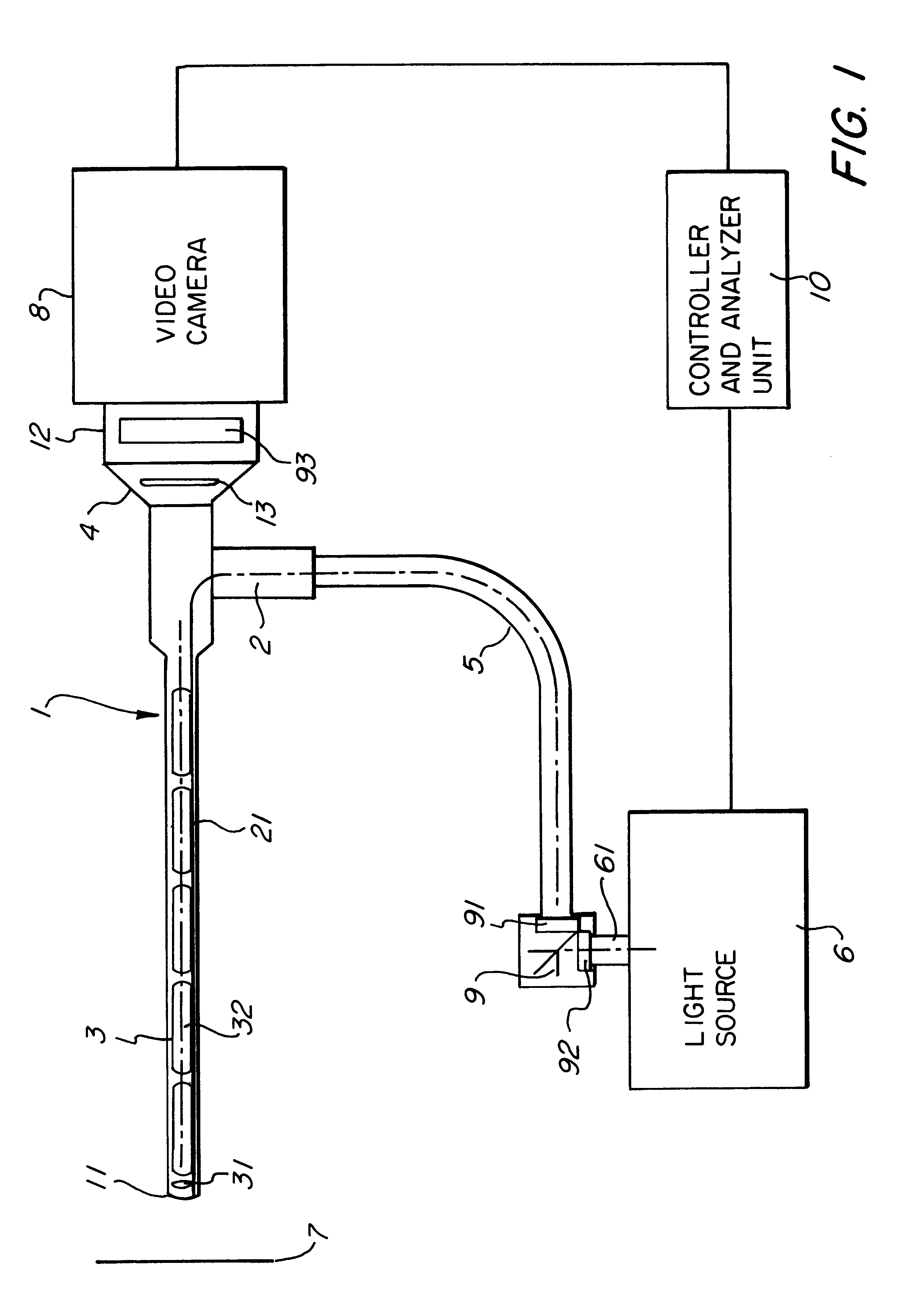
FIG. 1 shows a schematic illustration of the structure of an inventive device for endoscopic applications. The basic structure is known from the document WO 97 / 11636 which explicit reference is made to with respect to the explanations of all particulars not described here in details. For other applications such as those in microscopy the configuration must be modified correspondingly.

The reference numeral 1 denotes an endoscope which may be a rigid or a flexible endoscope. The endoscope 1 comprises--in a manner known per se--a connector 2 for the optical guide, an elongate element adapted to be introduced into a human or animal body (not illustrated here), and an eyepiece 4 (in the illustrated embodiment ).

The connector 2 for the optical guide of the endoscope 1 is connected via a flexible light guide 5 to a light source 6 which may comprise, for instance, a Xenon discharge tube. An optical guide 21, consisting of a fibre bundle, for instance, in the endoscope 1 passes the light fro...


PUM


Abstract

A method of and a device for the endoscopic fluorescence diagnosis of tissue, wherein the tissue is exposed to stimulating light via an endoscope for stimulation of fluorescence, which stimulating light is suitable, on account of its spectral distribution, to stimulate at least two different fluorescence modes in the tissue without filter switching in the stimulation beam path, and wherein the fluorescence light of the different fluorescence modes can be selectively observed.

Description

DESCRIPTIONThe present invention relates to a method of fluorescence diagnosis of tissue, particularly by endoscopy, as well as devices for performing fluorescence diagnoses. Such devices are also referred to as photodynamic diagnosis systems (PDD systems).These methods or devices, respectively, are employed for the "in vivo" diagnosis operating on a reaction induced by light in biologic tissue by an endogenic or exogenic photo sensitising agent; such methods and devices can be employed in particular for the (early) diagnosis of tumours and for tumour localisation.FundamentalsFor triggering a light-induced reaction in biologic systems a photo sensitising agent (also referred to as photo sensitizer) can be administered to the patient in a concentration of a few mg / kg of the body weight. Typical photo sensitizers display a basic hemato-porphyrin structure such as the substances Photofrin and Photosan-3. Another photo sensitizer that is frequently used in urology and dermatology is del...

Claims


Application Information

Patent Timeline
21 Jan 2003
Publication
US6510338B1
IPC
A61B5/00; A61B1/05; A61B1/04
CPC
A61B1/00186; A61B1/043; A61B5/0084; A61B1/0646; A61B5/0071; A61B1/05; A61B1/0638
Inventors
IRION, KLAUS M.; ERHARDT, ANDRE