Apparatus for directional drilling

a technology for directional drilling and apparatus, applied in the direction of drilling accessories, directional drilling, drilling machines and methods, etc., can solve the problems of complex sensor system and correspondingly complicated guidance mechanism, expensive and unreliable, and require several sets of pressure pads, etc., to achieve stable directional drilling and stable use.

Inactive Publication Date: 2003-02-11
DEVICO AS
View PDF9 Cites 24 Cited by
  • Summary
  • Abstract
  • Description
  • Claims
  • Application Information

AI Technical Summary

Benefits of technology

The directional drill according to the invention is significantly simpler, and thereby more sturdy in use, than those previously known. This also gives the possibility to ensure a stable directional drilling by means of simple adjustment steps. Further details of the invention are disclosed by the example below.

Problems solved by technology

A significant disadvantage with this known solution is that it requires several sets of pressure pads in rows in the length direction of the tool.
This solution, however, requires a complicated sensor system and a correspondingly complicated guidance mechanism, for the supply of pressure media to the several pressure pads.
It is therefore costly and unreliable.

Method used


Image

  • Apparatus for directional drilling
  • Apparatus for directional drilling
  • Apparatus for directional drilling

Examples


Embodiment Construction

In the following the invention is described in more detail with reference to the accompanying drawings, where

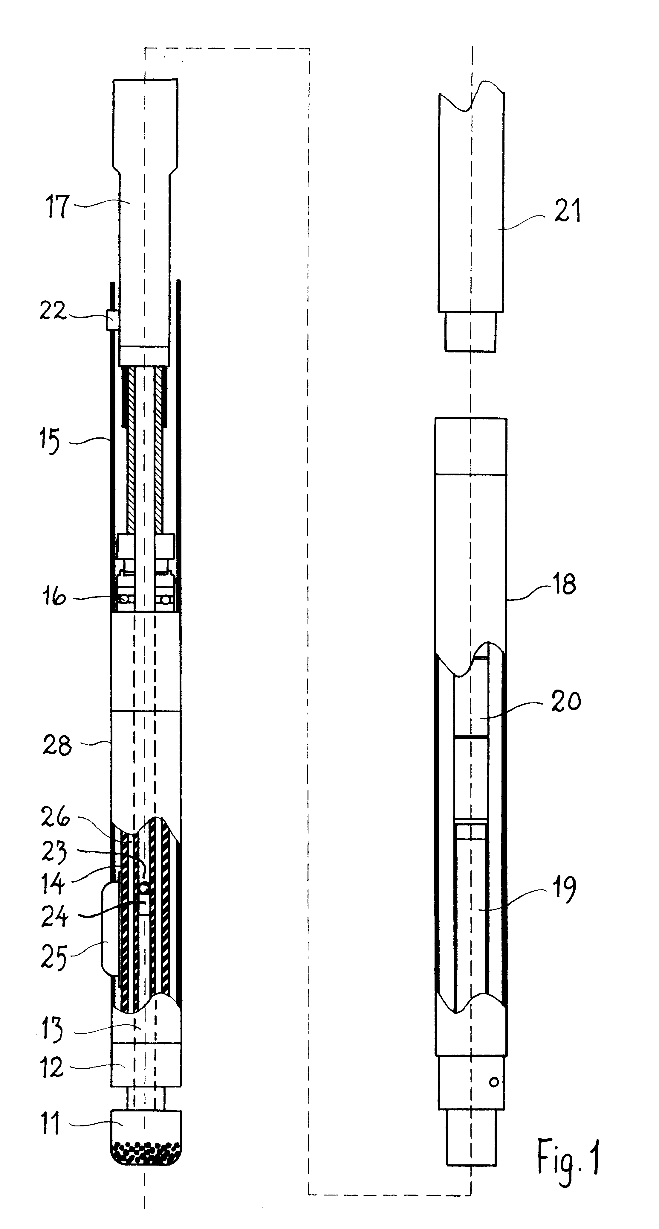
FIG. 1 is a side view of a section of a directional drill according to the invention,

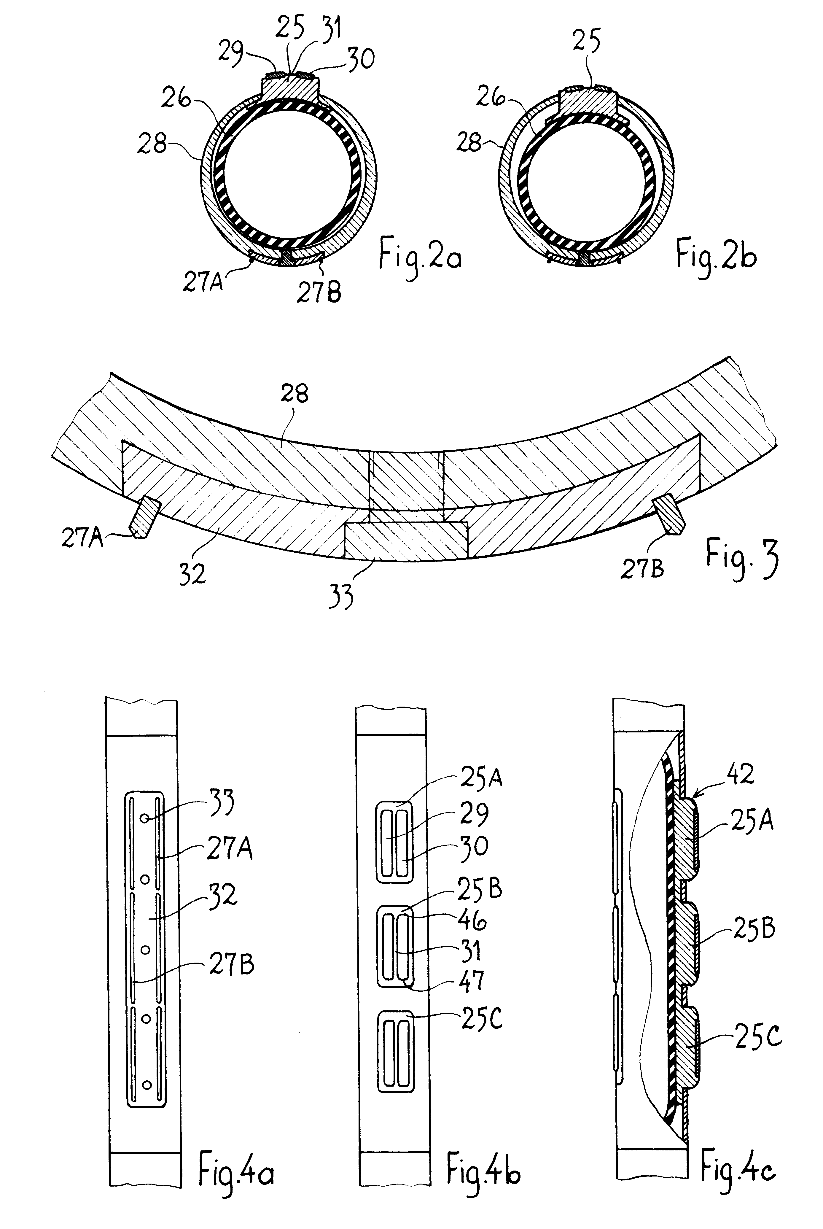
FIGS. 2a and 2b are sections of an embodiment of the invention, showing the design and position of a pressure pad and guidance ribs, with the pressure pad in an extended and retracted position respectively.

FIG. 3 shows a section of FIGS. 2a and 2b in a larger scale, illustrating how the guidance ribs are built-in,

FIGS. 4a-c show different side views, partly sectioned, of a part of a packer tube with three pressure pads.

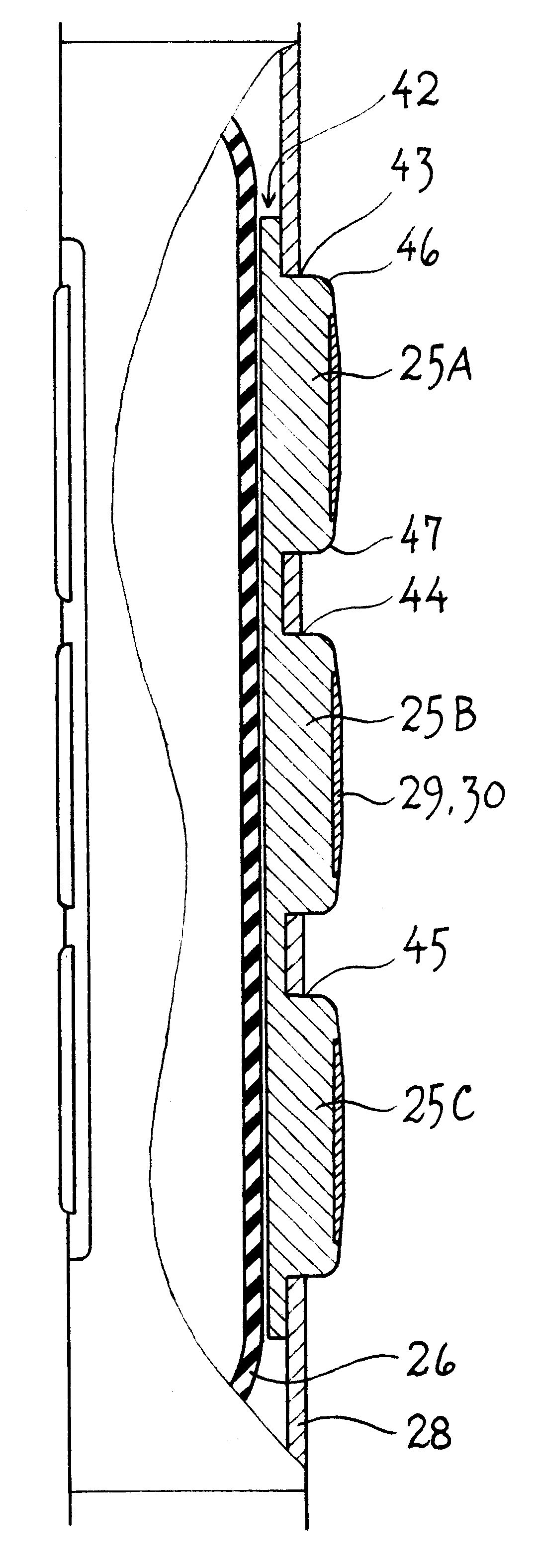
FIG. 5 shows an enlarged section of FIG. 4c, and

FIG. 6 shows a block diagram for a guidance system for selective activation of the packer-unit.

In FIG. 1 a directional drill is illustrated with a leading drill bit 11, which is connected to a drive shaft 13. A bearing housing 12, a packer unit 14 and a packer tubing 28, the back end of which is connected to an outer tubing 15, su...


PUM


Abstract

Grip and guiding device for directional drilling, in order to drill straight or curved holes with a predetermined path. The device includes a drill string (11-21) comprising parts which rotate during drilling, including a drill bit (11) or a water hammer on its front end and a non-rotating packer unit (14) with a packer tubing (28) comprising one or several projecting pressure pads (25,31-32) arranged behind the drill bit (11) or the water hammer. The pressure pad or pads are arranged to be pressed out towards the drill hole wall by means of the pressure from a drill fluid when this exceeds a certain level. The pressure pad (25) or the pressure pads (25A-25C) may be arranged asymmetrically and/or affects the packer tubing (28) asymmetrically, e.g. by having different heights. The pressure pad(s) force guiding ribs on the opposite side into the hole wall in order to prevent rotation of the packer unit (14). The pressure pad or pressure pads can on deactivation be withdrawn for performing linear drilling.

Description

The invention relates to a grip and guiding device for a directional drill for geotechnical drilling, especially rock drilling, more precisely a device as defined by the introductory part of claim 1, particularly for directional drilling with high precision in sedimentary species of rock.A directional drill is described in NO C 168 962 which is provided with a locking device or packer which is supplied with drilling fluid under pressure in order to push out locking elements or pressure pads which can be brought in contact with the bore wall and lock the directional drill relative to the wall, so that rotation of the outer tubing of the directional drill is avoided. Such pressure pads may be utilised for locking an eccentric housing in a certain position or be used to bring upon the drill bit a skewed position, for thereby performing directional drilling.From NO patent application Ser. No. 962744 is known a guidance tool for a rock drill where several pressure pads are arranged in at...

Claims


Application Information

Patent Timeline
Patent Type & Authority Patents(United States)
IPC IPC(8): E21B7/04E21B7/06E21B7/10E21B17/10
CPCE21B7/068E21B7/062
Inventor TOKLE, VICTOR
Owner DEVICO AS
Why Eureka
Try Eureka