Fuel injection valve

a fuel injection valve and valve body technology, applied in the direction of valve operating means/release devices, machines/engines, mechanical equipment, etc., can solve the problems of small valve needle lift, small force applied to the opening of the valve needle, and limiting the lift of the valve needle attainable by the bending elements

Inactive Publication Date: 2003-02-11
ROBERT BOSCH GMBH
View PDF11 Cites 6 Cited by
  • Summary
  • Abstract
  • Description
  • Claims
  • Application Information

AI Technical Summary

Problems solved by technology

In the fuel injection valve known from German Patent 38 00 203 C2, it is disadvantageous that the ceramic plate and the conductive films are layered one above the other in the direction of movement of the valve closing body, as a result of which each bending element only produces a small valve needle lift and only a small force can be applied for opening the valve needle.
A further disadvantage is that the bending elements have a central bore through which the valve needle projects, so that when the bending elements are activated, high bending stresses occur in the central area of the bending el

Method used


Image

  • Fuel injection valve
  • Fuel injection valve
  • Fuel injection valve

Examples


Embodiment Construction

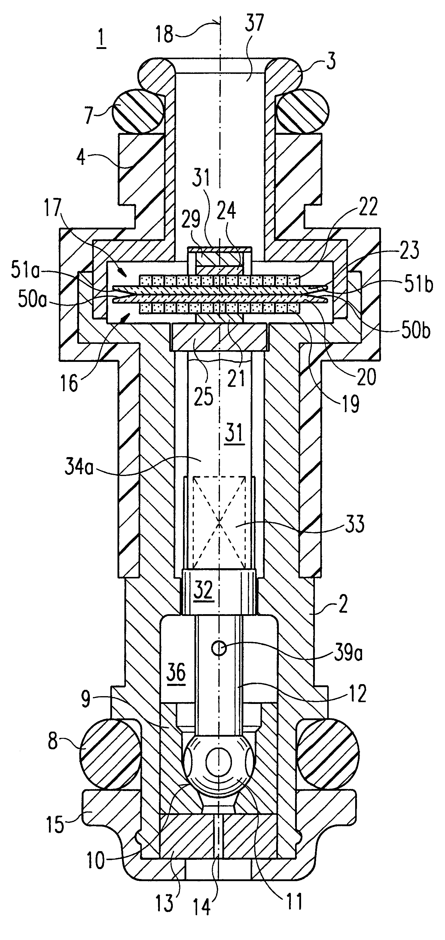
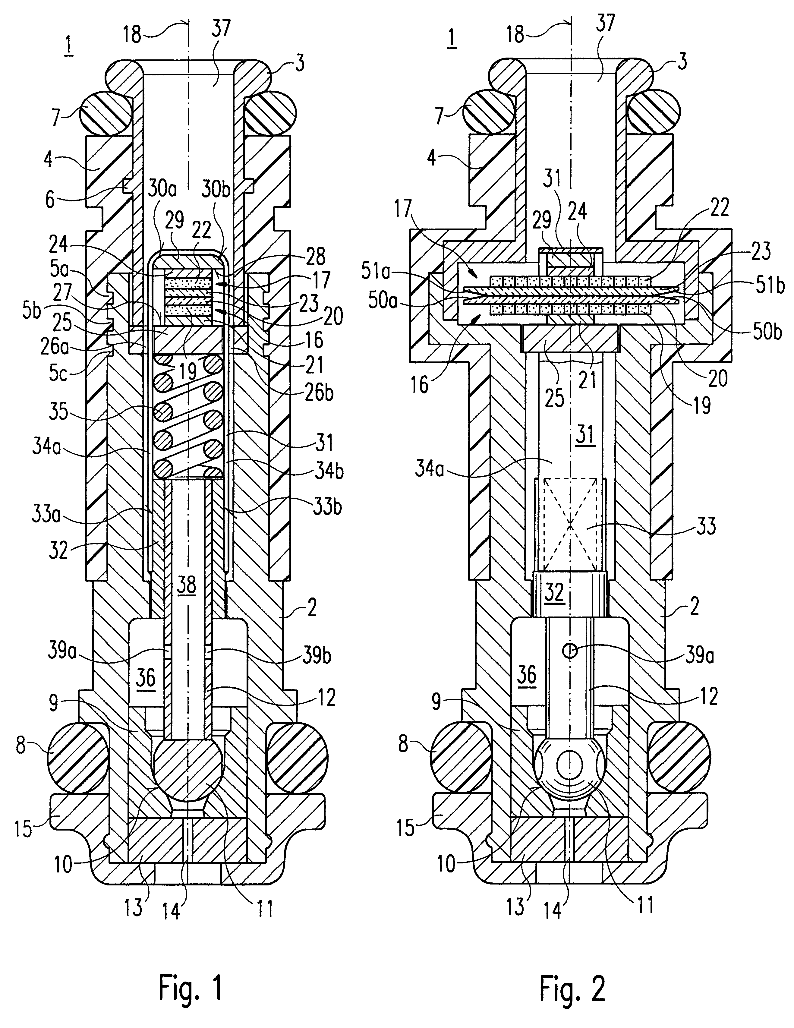
FIG. 1 shows a fuel injection valve 1 of the present invention in a simplified axial sectional view. Fuel injection valve 1 is used in particular for the direct injection of fuel, in particular gasoline, into a combustion chamber of an internal combustion engine with mixture-compression spark ignition as a so-called gasoline direct-injection valve. However, fuel injection valve 1 of the present invention is also suitable for other applications, in particular for injecting fuel into an intake manifold of the internal combustion engine.

Fuel injection valve 1 has a valve seat holder 2 connected to a fuel intake connecting piece 3. Valve seat holder 2 and fuel intake connecting piece 3 are surrounded by a plastic jacket 4 at least in sections, plastic jacket 4 together with valve seat holder 2 forming a housing of fuel injection valve 1. Plastic jacket 4 is preferably sprayed around valve seat holder 2 and fuel intake connecting piece 3. In order to produce a connection having positive ...


PUM


Abstract

A fuel injection valve, in particular an injection valve for fuel injection systems of internal combustion engines, has a valve closing body that can be activated by an activation device with the aid of a valve needle, the valve closing body interacting with a valve seat surface to produce a sealing seat, and the activation device having at least one piezoelectric first bending element for producing a valve needle lift of the valve needle, the first bending element bending when the activation device is activated. In this context, the bending element is made of a plurality of piezo elements stacked in a longitudinal direction of the first bending element, internal electrodes arranged between the piezo elements being oriented perpendicular to the longitudinal direction of the bending element.

Description

RELATED ARTThe present invention starts from a fuel injection valve according to the type of the main claim.A fuel injection valve having a valve closing body that can be activated by an activation device by means of a valve needle and that interacts with a valve seat surface to produce a seat is known from German Patent 38 00 203 C2. In this case the activation device for producing a valve needle lift has two piezoelectric bending elements that bend when the activation device is activated. In this context the bending elements are oriented in their longitudinal direction perpendicular to the direction of movement of the valve closing body. Each of the activating elements has a ceramic plate arranged between two conductive films. The ceramic plate and the conductive films are thus stacked in the direction of movement of the valve closing body. To activate the activation device, a voltage applied between the conductive films acts on the ceramic plate causing the ceramic plate to bend....

Claims


Application Information

Patent Timeline
IPC IPC(8): F02M51/06
CPCF02M51/0603
Inventor BOECKING, FRIEDRICH
Owner ROBERT BOSCH GMBH
Why Eureka
Try Eureka