
Electric-power supply with rectifier

a technology of rectifier and electric power supply, applied in the direction of electric variable regulation, process and machine control, instruments, etc., to achieve the effect of reducing the overall dimension, simplifying the fabrication process, and simple conformation

Active Publication Date: 2005-08-23
ABB (SCHWEIZ) AG
View PDF7 Cites 17 Cited by
  • Summary
  • Abstract
  • Description
  • Claims
  • Application Information

AI Technical Summary

Benefits of technology

[0005]The purpose of the present invention is to provide an electric-power supply in which the electronic components and the electrical power connections at output from the rectifier assume a particularly simple conformation, with simplification in the fabrication process, reduction in the overall dimensions, as well as reduction in the costs of construction and in electromagnetic emissions.
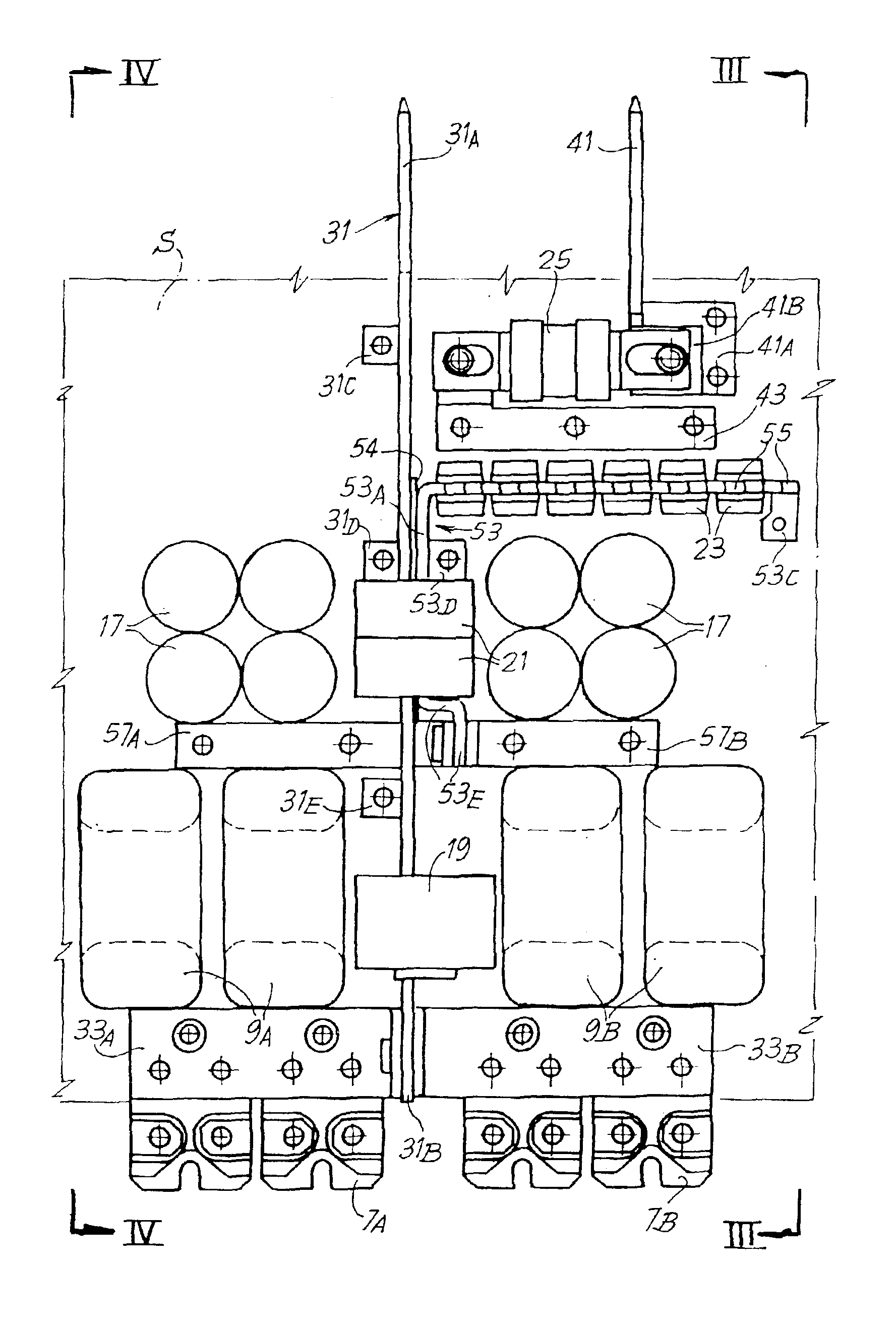
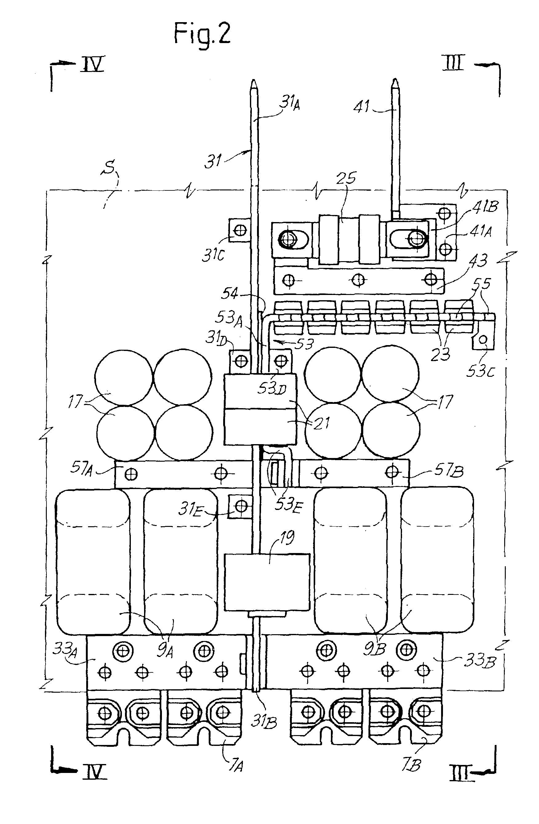
[0007]As will appear clearly from the description of an example of embodiment, with a configuration of this type it is possible to obtain a neat assembly of the electronic components at output from the rectifier, with substantial reduction in the overall dimensions and drastic simplification of the assembly of the various components.
[0014]Advantageously, according to a preferred embodiment of the invention, around the area of the first bar and of the third bar, where the mechanical connection between them is located, there is set a common choke. This choke constitutes a further electronic component carried by the bars that form the output line of the power supply. This configuration further simplifies the construction of the various components and their assembly.

Problems solved by technology

One of the difficulties in making electric-power supplies of this type is the wiring, i.e., the connection of the various output components set between the rectifier proper and the positive and negative connections to the load.

Method used


Image

  • Electric-power supply with rectifier
  • Electric-power supply with rectifier
  • Electric-power supply with rectifier

Examples


first embodiment

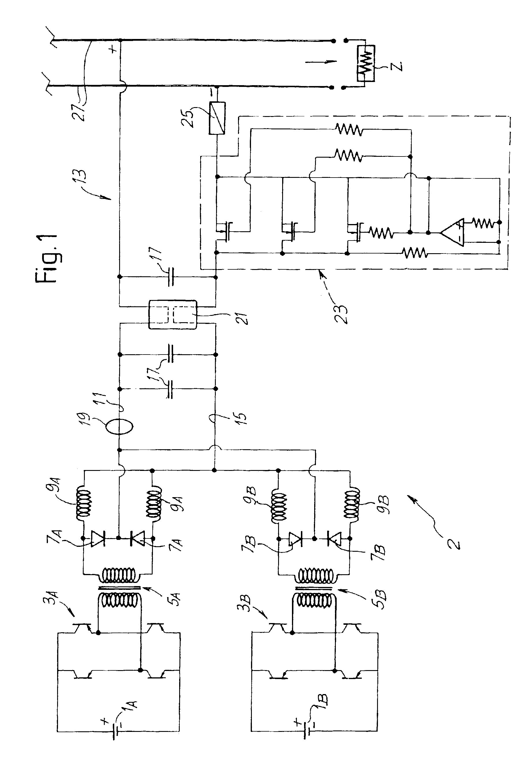
[0026]One first embodiment of the power supply of the present invention is represented in FIGS. 1 to 5. FIG. 1 reproduces a simplified diagram of a power supply 2, which, in the example illustrated, has two rectifiers set in parallel. On the other hand, it is to be understood that the concept underlying the present invention can be implemented also with a power supply having a single rectifier.

[0027]The reference numbers 1A and 1B indicate as a whole the DC voltage sources at input to the rectifiers. The reference numbers 3A and 3B designate as a whole the switches in bridge configuration; whilst 5A and 5B designate the output transformers of each rectifier. Each rectifier has two output diodes 7A and 7B, respectively, and two output chokes 9A and 9B. The rectifiers are connected in parallel and hence the two pairs of output diodes 7A, 7A and 7B, 7B are connected to the positive side 11 of an output line, designated as a whole by 13 and of which the reference number 15 designates th...


PUM


Abstract

An electric-power supply incorporates an electronic card with at least one rectifier and one output line of the rectifier. The output line is formed of at least one first bar made of conductive material, terminating with one first output end, and at least one second bar made of conductive material, terminating with one second output end. The two output ends form the positive and negative output poles of the power supply for connection to a load. Means are provided for electrical and mechanical connection for the first bar and the second bar to the card, and on at least one of the two bars is carried at least one electronic component of said rectifier.

Description

[0001]This application claims benefit of co-pending European Patent Application Ser. No. 02425390.8 filed Jun. 17, 2002, entitled “Electric-Power Supply with Rectifier” which is hereby incorporated by reference.[0002]Be it known that we, Antonio Canova, a citizen of Italy, residing at Via Po 79 / 4 , 52925 Montevarchi, Arezzo Italy; Mauro Piazzesi, a citizen of Italy, residing at Via E. Tarantelli 4, 52028 Terranuova Bracciolini, Arezzo Italy; have invented a new and useful “Electric-Power Supply with Rectifier.”BACKGROUND OF THE INVENTION[0003]The present invention relates to an electric-power supply comprising a rectifier and an output line for the connection of the rectifier to a load.[0004]One of the difficulties in making electric-power supplies of this type is the wiring, i.e., the connection of the various output components set between the rectifier proper and the positive and negative connections to the load.SUMMARY OF THE INVENTION[0005]The purpose of the present invention is...

Claims


Application Information

Patent Timeline
Patent Type & Authority Patents(United States)
IPC IPC(8): H02M3/28H02M7/00H02M3/24H05K7/14
CPCH02M3/285H02M7/003H05K7/1432H05K7/14329
Inventor CANOVA, ANTONIOPIAZZESI, MAURO
Owner ABB (SCHWEIZ) AG
Learn More