Device and mechanism for transmission of radial forces between the central and end regions of this device

a technology of radial force transmission and central and end regions, which is applied in mechanical devices, transportation and packaging, couplings, etc., can solve the problems of large increase in the mass of fittings, and the type of increase in mass is usually incompatible with the required performance of aircra

Inactive Publication Date: 2003-03-11
AIRBUS OPERATIONS (SAS)
View PDF7 Cites 16 Cited by
  • Summary
  • Abstract
  • Description
  • Claims
  • Application Information

AI Technical Summary

Problems solved by technology

This results in a large increase in the mass of the fitting to limit stresses and deformations within it.
How

Method used


Image

  • Device and mechanism for transmission of radial forces between the central and end regions of this device
  • Device and mechanism for transmission of radial forces between the central and end regions of this device
  • Device and mechanism for transmission of radial forces between the central and end regions of this device

Examples


Embodiment Construction

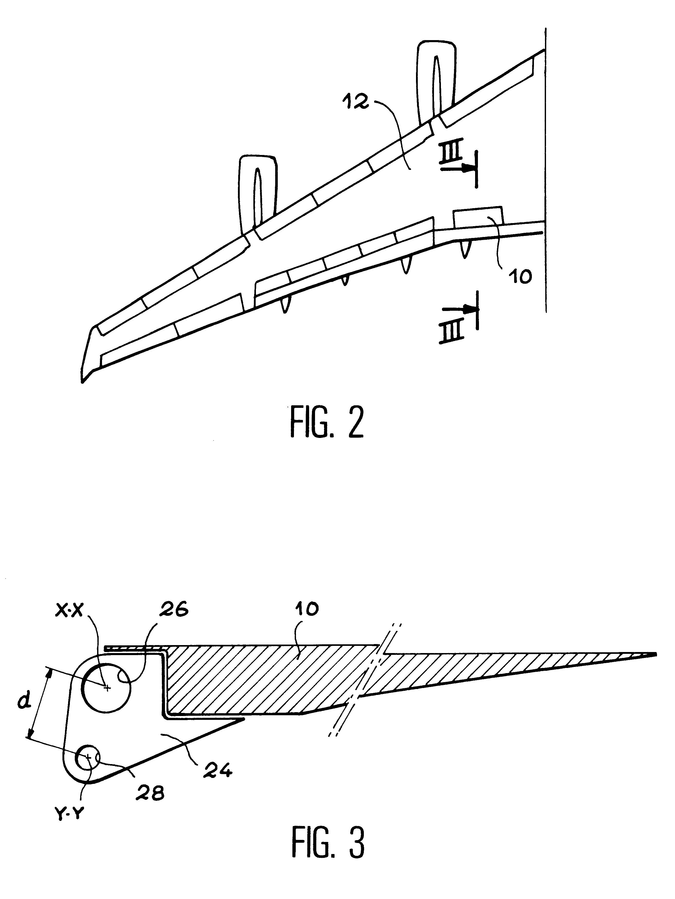
As shown in FIG. 2 in the particular case of an aircraft wing, an aircraft normally comprises a large number of control surfaces. In this case, as in the rest of the text, this refers to all types of flaps, ailerons, etc., that are articulated to a fixed part of the aircraft such as the wing, vertical stabilizer, tail fins or the fuselage, so that the pilot can modify some flight characteristics such as the heading, speed, lift, etc.

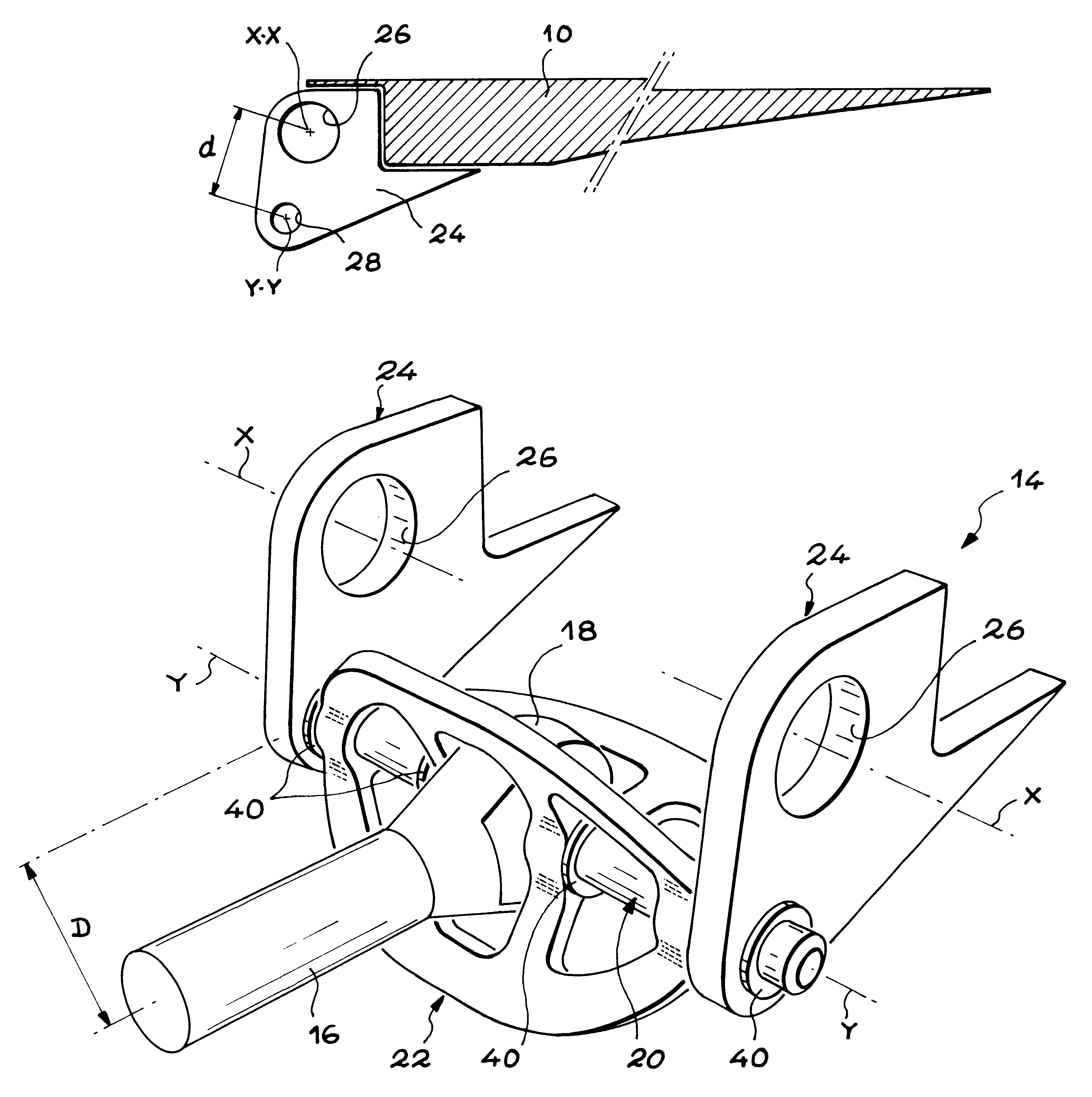
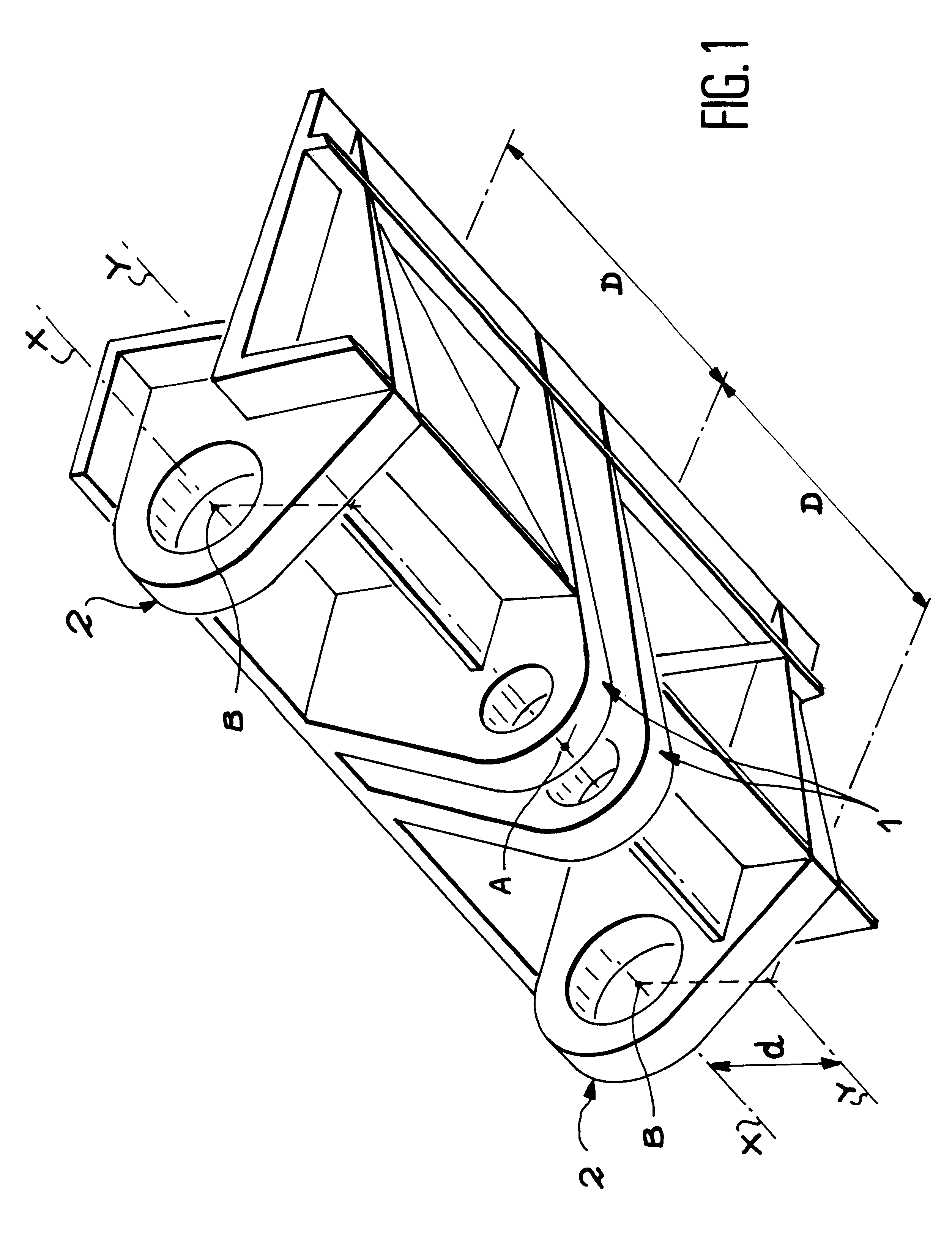
Each control surface such as that shown by reference 10 in FIG. 2 can be articulated to the corresponding fixed part through a force transmission device according to the invention. In the embodiment shown as an example in FIGS. 2 to 5, the fixed part is composed of the wing 12 of the aircraft and the force transmission mechanism in general is denoted as reference 14.

The force transmission mechanism 14 is a structure that pivots the control surface 10 on wing 12 and transmits forces that may be applied by an aircraft servocontrol (not shown) to the contro...


PUM


Abstract

A device (22) fitted with ribs is placed on a cylindrical rod (20) so that it is fixed to it in bending. The device (22) is formed of at least three ribs connected to each other at their ends, and at least one pair of elements in the form of a star connecting the ribs together, at least close to its central region. This device enables the rod (20) to apply an approximately radial force to the center of the rod through an actuator onto webs (24) bearing on its ends, minimizing the mass for a given spacing of the webs (24). The device is particularly applicable to the control of aircraft control surfaces.

Description

The invention relates to a device centered on a predetermined longitudinal axis designed to transmit forces between a central region and end regions of the said device.The invention is also applicable to a mechanism comprising such a device associated with a cylindrical rod acting as a pivot pin, and forces are transferred between the pivot pin and two parts, one of the parts applies forces to the pivot pin and the pivot pin applies forces to the other part.The invention also relates to application of a mechanism of this type to the transmission of forces between a linear actuator mounted on a fixed aircraft structure and a control surface that can pivot about the fixed structure, around an axis of rotation parallel to the longitudinal axis of the force transmission part and offset from this axis. In particular, the fixed structure may be an element of a wing, vertical stabilizer, tail fins or the fuselage of the aircraft.STATE OF THE ARTAn aircraft control surface is normally artic...

Claims


Application Information

Patent Timeline
IPC IPC(8): B64C9/00B64C9/02B64C13/00B64C13/24F16C11/04
CPCB64C9/02F16C11/045B64C13/24Y10T403/32861F16C2326/43
Inventor MILLIERE, JEROME
Owner AIRBUS OPERATIONS (SAS)
Why Eureka
Try Eureka