Heat dissipating fan with an oil guide

a technology of heat dissipating fans and oil guides, which is applied in the direction of non-positive displacement fluid engines, pump components, piston pumps, etc., can solve the problems of high pressure in the chamber, inconvenient operation, and inability to releas

Inactive Publication Date: 2003-04-08
HSIEH HSIN MAO
View PDF8 Cites 39 Cited by
  • Summary
  • Abstract
  • Description
  • Claims
  • Application Information

AI Technical Summary

Problems solved by technology

However, during the assembly of the conventional heat dissipation fan, the air contained in the cavity (521) cannot be released and high pressure will build up in the chamber.
In addition, the lubricant easily flows out due to the pressure in the chamber, so the bushing (70) will easily dry out.

Method used


Image

  • Heat dissipating fan with an oil guide
  • Heat dissipating fan with an oil guide
  • Heat dissipating fan with an oil guide

Examples


Embodiment Construction

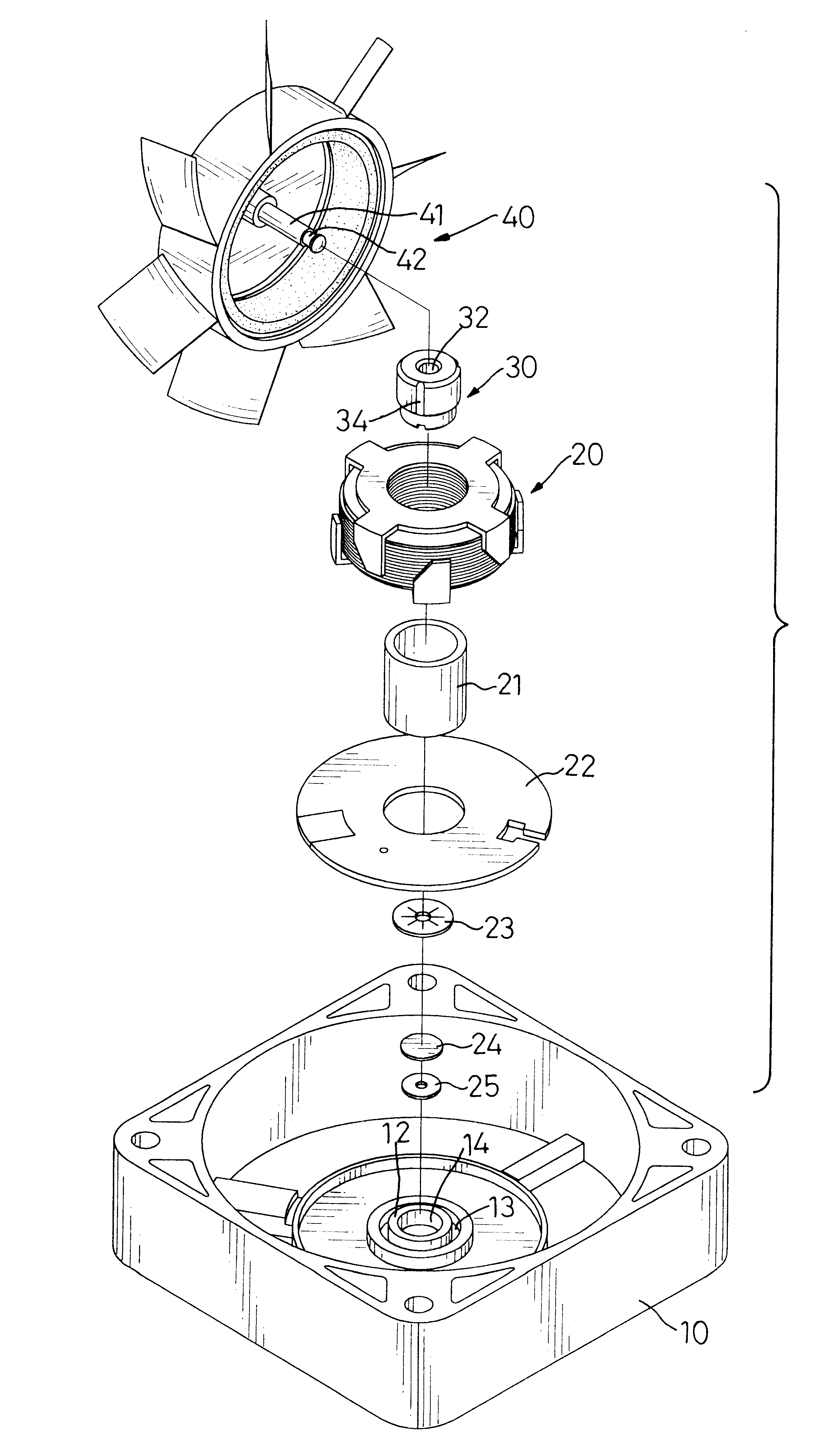
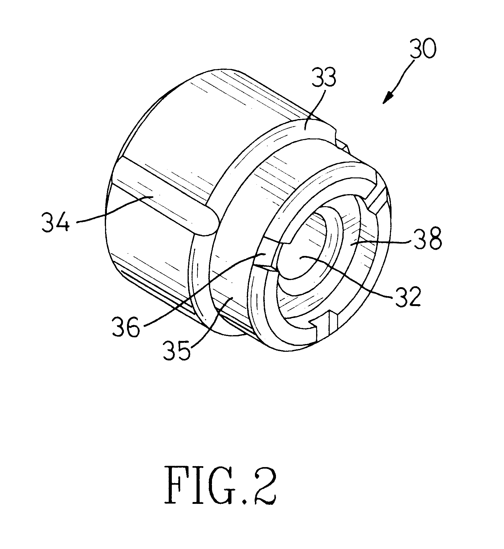
With reference to FIGS. 1 and 3, a heat dissipation fan in accordance with the present invention comprises a casing (10), a stator (20), a lubricating bushing (30) and a fan (40). A chamber (not numbered) is defined in the casing (10) to receive the fan (12). A base (12) with a cavity (14) is formed in the casing (10). An annular groove (13) is defined around the base (12).

The stator (20) is securely mounted in the chamber of the casing (10). A sleeve (21) is pressed into the stator (20) and is securely mounted in the casing (10) by pressing one end of the sleeve (21) into the annular groove (13). A circuit board (22) is attached to the stator (20).

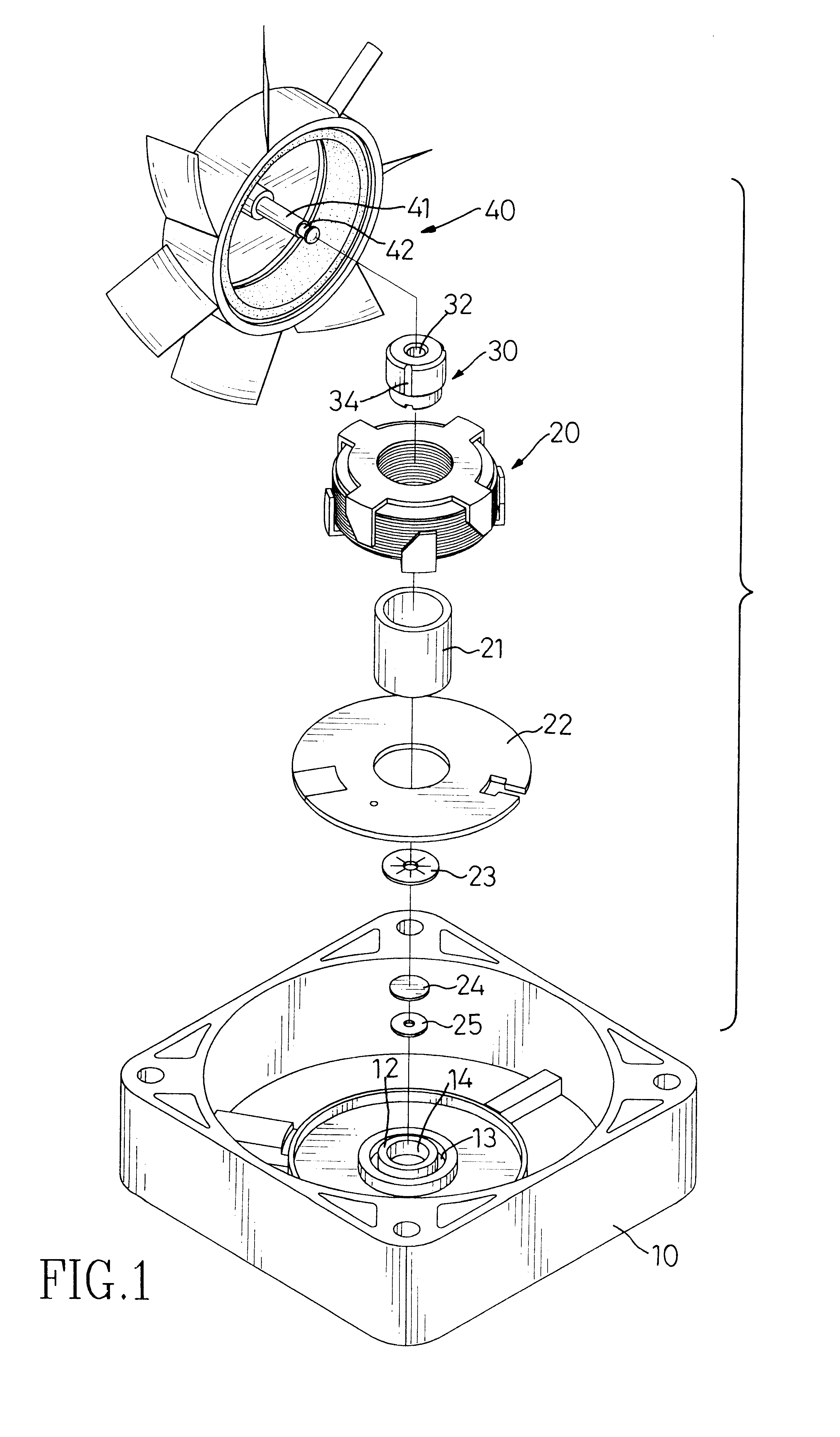
With reference to FIGS. 1, 2, 3 and 4, the lubricating bushing (30) contains lubricant and is securely mounted in the sleeve (21). A passage (32) is defined through the lubricating bushing (30). A protrusion (35) with a diameter smaller than that of the lubricating bushing (30) axially extends from the lubricating bushing (30), such that ...


PUM


Abstract

A heat dissipation fan has a casing, a stator, a lubricating bushing and a fan. The stator is secured to the casing with a sleeve. The lubricating bushing has lubricant contained therein and is mounted in the sleeve. The fan is rotatably mounted in the casing and has a permanent magnet to be a rotor. A shaft extends from the fan and through a passage defined through the lubricating bushing. A locking disk is securely mounted on the shaft to hold the lubricating bushing. An oil guide is arranged on the lubricating bushing. Accordingly, the air in the cavity can be released from the oil guide during the assembly of the dissipation fan. The oil guide can keep oil from flowing out of the sleeve and drying out the lubricating bushing. The useful life of the dissipation fan is prolonged.

Description

1. Field of the InventionThe present invention relates to a heat dissipating fan, and more particularly to a heat dissipating fan with an oil guide for a lubricating bushing.2. Description of Related ArtWith reference to FIG. 5, a conventional heat dissipation fan in accordance with the prior art comprises a casing (50), a stator (60), a lubricating bushing (70) and a fan (80). The fan (80) is rotatably mounted in the casing (50). The stator (60) with an electromagnet and a circuit board (62) is securely mounted in the casing (50). A permanent magnet (not numbered) is mounted in the fan (80) to be a rotor, such that the fan (80) can rotate due to the interaction between the magnetic forces in stator (60) and the permanent magnet. A sleeve (61) pressed into the stator (60) is engaged with an annular groove (53) defined around a base (52) formed in the casing (50). A lubricating bushing (70) has a lubricant impregnated in the material forming the lubricating bushing (70). The lubricat...

Claims


Application Information

Patent Timeline
Patent Type & Authority Patents(United States)
IPC IPC(8): F04D29/04F04D29/06
CPCF04D29/063F04D29/051F04D25/062F04D29/668
Inventor HSIEH, HSIN-MAO
Owner HSIEH HSIN MAO
Why Eureka
Try Eureka