Speaker enclosure and mounting method for isolating and insulating faceplate and speakers from a surrounding mounting surface

a technology for speakers and mounting surfaces, applied in the field of speaker enclosures or cabinets, can solve problems such as absorption, interference, or other undesirable sound distortion, and drywall cracks or failures

Inactive Publication Date: 2003-04-22
MS ELECTRONICS
View PDF24 Cites 24 Cited by
  • Summary
  • Abstract
  • Description
  • Claims
  • Application Information

AI Technical Summary

Problems solved by technology

Unfortunately, the speakers are typically mounted upon or in contact with the drywall, resulting in drywall cracks or other failure due to vibrations transmitted by the operational speakers.
Furthermore, direct speaker-to-drywall contact can result in absorption, interference, or other undesirable sound distortion.
Unfortunately, an enclosure and its speakers, weighing a combined thirty or more pounds, can cause the mounting surface to bow or fail, again resulting in drywall cracks or failure and possibly allowing the enclosure to fall.
Furthermore, adjacent wall and ceiling structures can cause undesirable sound distortion or vibrations and are subject to damage when transmitted speaker-generated vibrations reach certain magnitudes or frequencies.
Such vibration can also lead to a loosening and separation of the enclosure mount from the mounting surface.
Unfortunately, though the enclosure may be mounted to wall studs, contact between the faceplate and drywall can still cause bowing, cracking or failure thereof, particularly where the faceplate is over tightened thereupon during installation.
Furthermore, even though the faceplate does not depend directly from the drywall, speaker vibrations can still be transmitted from the enclosure via the mounting studs to the drywall, which, again, may cause cracking, sound distortion, or other undesirable effects.

Method used


Image

  • Speaker enclosure and mounting method for isolating and insulating faceplate and speakers from a surrounding mounting surface
  • Speaker enclosure and mounting method for isolating and insulating faceplate and speakers from a surrounding mounting surface
  • Speaker enclosure and mounting method for isolating and insulating faceplate and speakers from a surrounding mounting surface

Examples


Embodiment Construction

, below.

A preferred embodiment of the present invention is described in detail below with reference to the attached drawing figures, wherein:

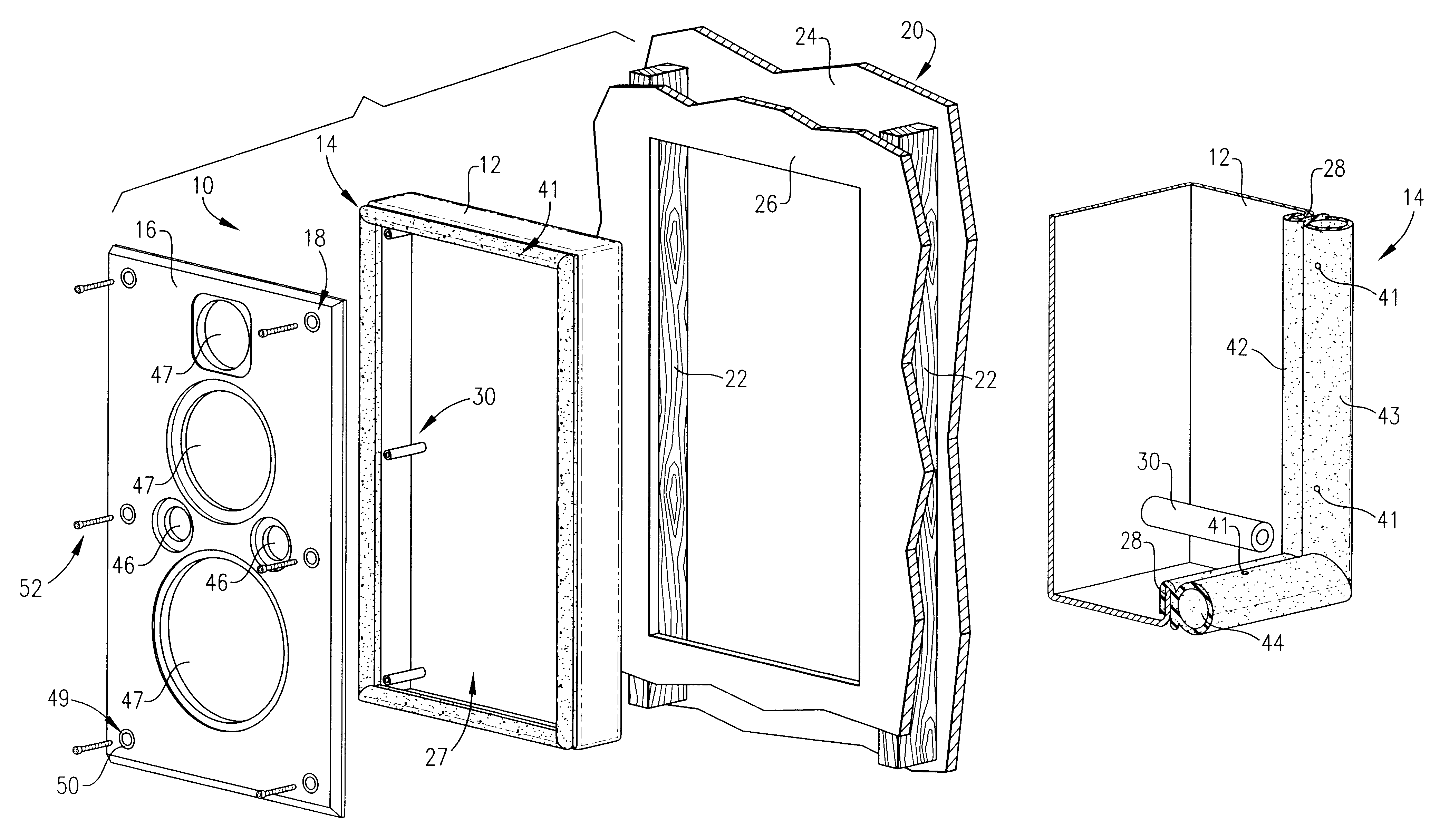
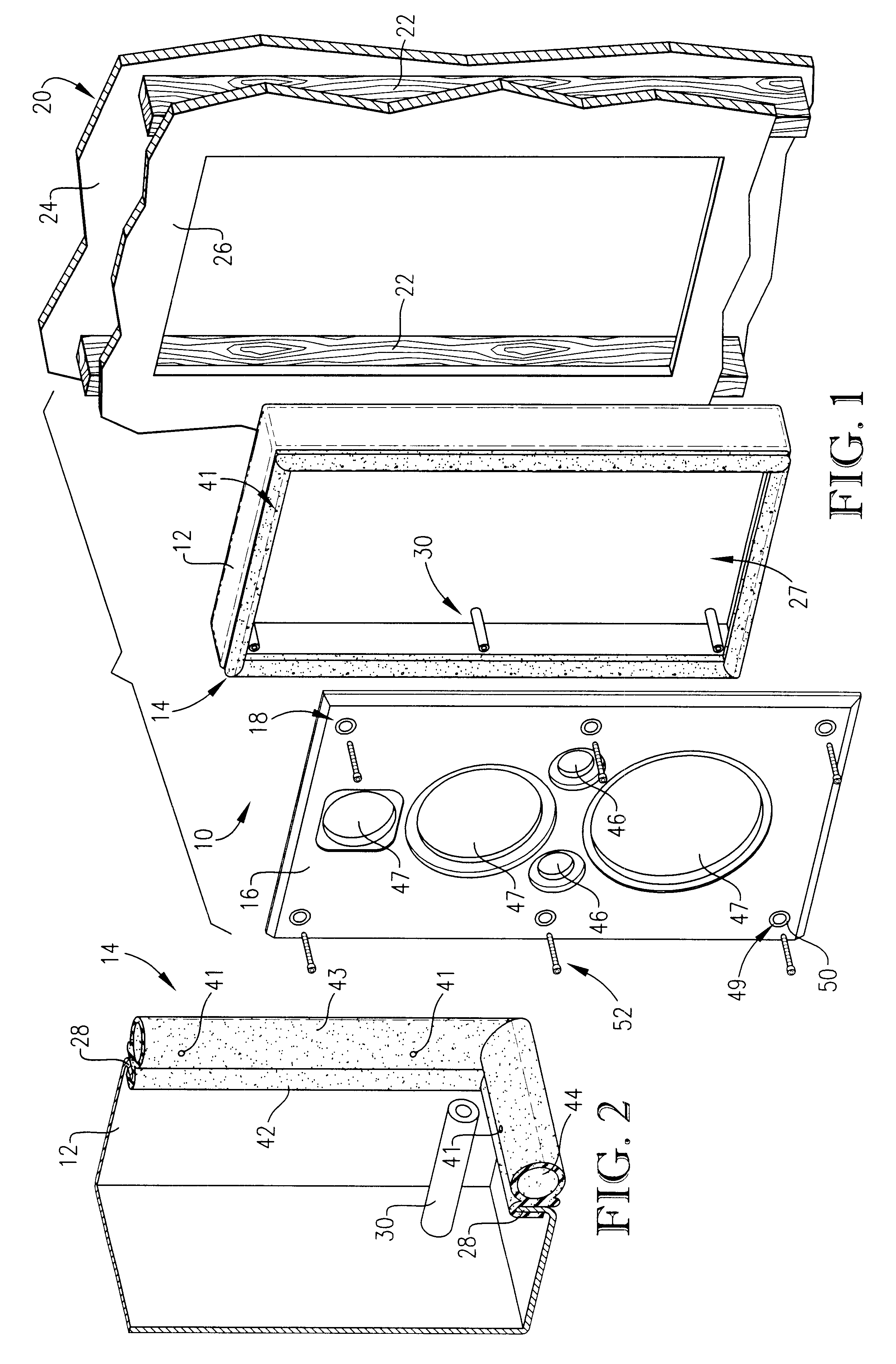
FIG. 1 is exploded isometric view of a preferred embodiment of the speaker enclosure of the present invention;

FIG. 2 is a fragmentary sectional view of a portion of the preferred speaker enclosure shown in FIG. 1;

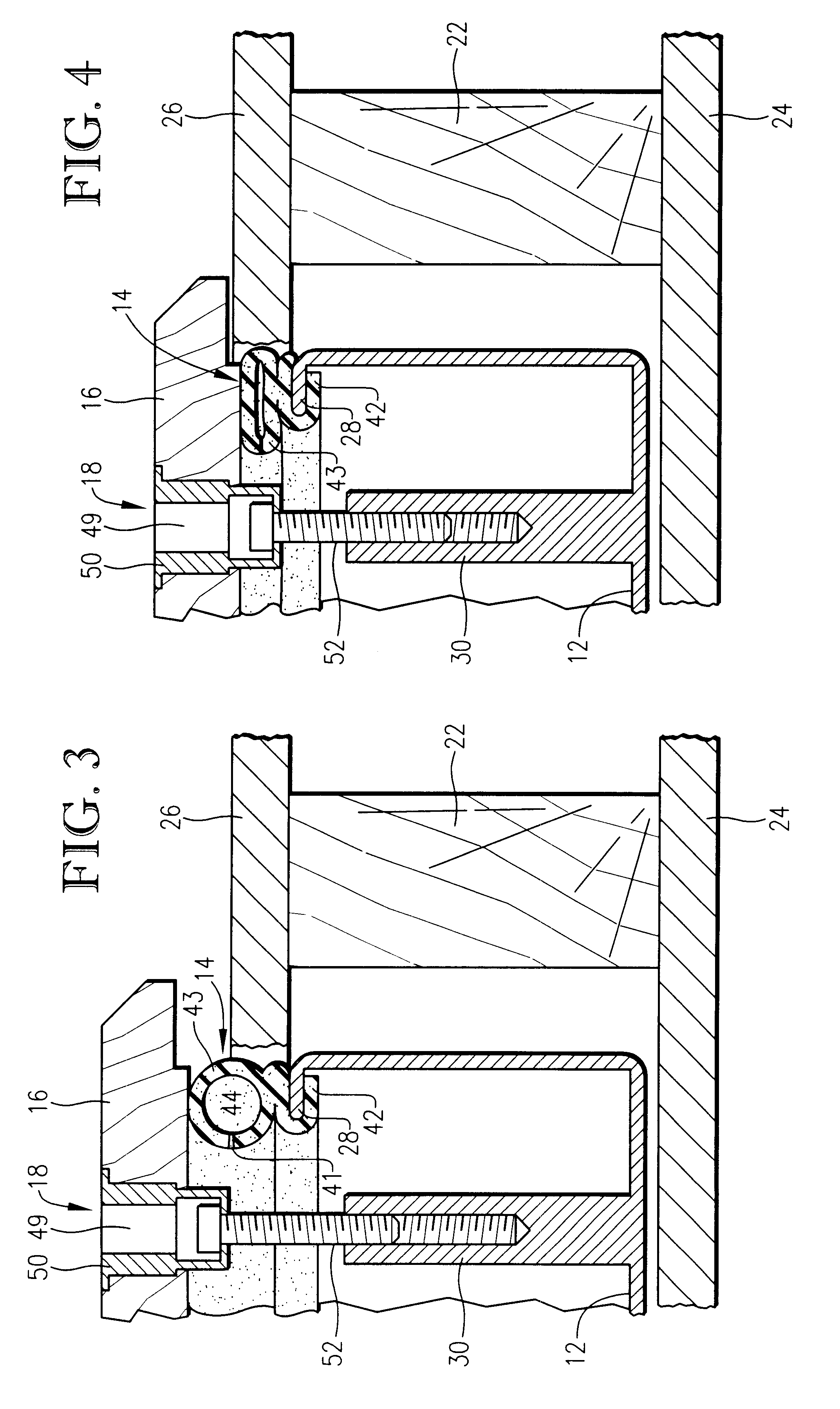
FIG. 3 is a fragmentary sectional view of the preferred speaker enclosure of FIG. 1 wherein the faceplate is in an initial mounting position with the isolating and insulating gasket uncompressed; and

FIG. 4 is a fragmentary sectional view of the preferred speaker enclosure of FIG. 1 wherein the faceplate is in a final mounting position with the isolating and insulating gasket compressed to provide the optimum degree of separation between faceplate and wall board.

DETAILED DESCRIPTION OF A PREFERRED EMBODIMENT

Referring to FIG. 1, a speaker enclosure 10 is shown constructed in accordance with a preferred embodiment of the present invention...


PUM


Abstract

A speaker enclosure (10) comprising a speaker box (12) having an opening (27) and adapted for mounting within a wall (20) upon a wall stud (22); a compressible gasket (14) affixed about the box opening (27); a faceplate (16); and a plurality of independently adjustable coupling mechanisms (18) for coupling the faceplate (16) with the box (12). The uncompressed gasket (14) protrudes beyond the wall surface (26) until the faceplate (16) is brought into contact with and compresses the gasket (14) by the coupling mechanisms (18) which may be independently adjusted to provide an optimum and substantially uniform degree of separation between faceplate (16) and wall (20), thereby reducing distortion, vibration, and damage due to undesirable contact therebetween.

Description

1. Field of the InventionThe present invention relates to speaker enclosures or cabinets recessedly mounted beneath a surface or within a structure. More particularly, the invention relates to a speaker enclosure adapted for in-wall mounting and having a suspending or isolating and insulating gasket providing an optimum or desirable degree of separation between the enclosure faceplate and the wall in which the enclosure is mounted so as to prevent sound distortion and wall damage due to improper installation or vibrations.2. Description of the Prior ArtThose with skill in the art of home theater systems and speaker enclosures or cabinets will appreciate that a number of strategically placed speakers are often desirable in order to produce the best sound. This is true, for example, in home theater systems employing left and right main, left and right surround, center, and sub-woofer speaker groupings, with each such grouping typically comprising a variety of individual specialized sp...

Claims


Application Information

Patent Timeline
Patent Type & Authority Patents(United States)
IPC IPC(8): H04R1/02
CPCH04R1/02H04R2201/021
Inventor COMBEST, CHRISTOPHER E.
Owner MS ELECTRONICS
Why Eureka
Try Eureka