
Method and apparatus for generating a template

a template and template technology, applied in the field of tools and hardware, can solve the problems of loss or damage in shipping, time delay due to shipping, waste of materials,

Inactive Publication Date: 2003-04-29
KLASS KEVIN M +1
View PDF27 Cites 32 Cited by
  • Summary
  • Abstract
  • Description
  • Claims
  • Application Information

AI Technical Summary

Problems solved by technology

Problems with this method include loss or damage in shipping, time delays due to shipping, waste of materials, cost of shipping, considerable labor to fabricate and considerable storage space required.
The problems with these and other measurement methods include: bubble level readings can be inaccurate; measuring does not account for convex or concave walls or floors; and without a physical template at the installation site there is no way to test ingress clearances for the glass or mirror to get to the installation site and in situ from the outside.
In addition, levels are useless when fitting a template on ships or houseboats.
However, none of the above references, alone or in combination, provide a circular compass and vernier that can be placed flush into a corner to define the angle therein.
In addition, none of the references, alone or in combination, provide a plurality of expandable continuous straight edges with readouts on each side, that when attached form intersecting lines.
Furthermore, none of the references provide an apparatus that will lay flat on the surface to be measured and the surface of the material to be cut.
Also, none of the references have the capability to display the corner angles and side length dimensions of the space being measured, enabling the user to communicate those angles and dimensions only (and not the physical template itself) to another location for reproduction of the template.

Method used


Image

  • Method and apparatus for generating a template
  • Method and apparatus for generating a template
  • Method and apparatus for generating a template

Examples


Embodiment Construction

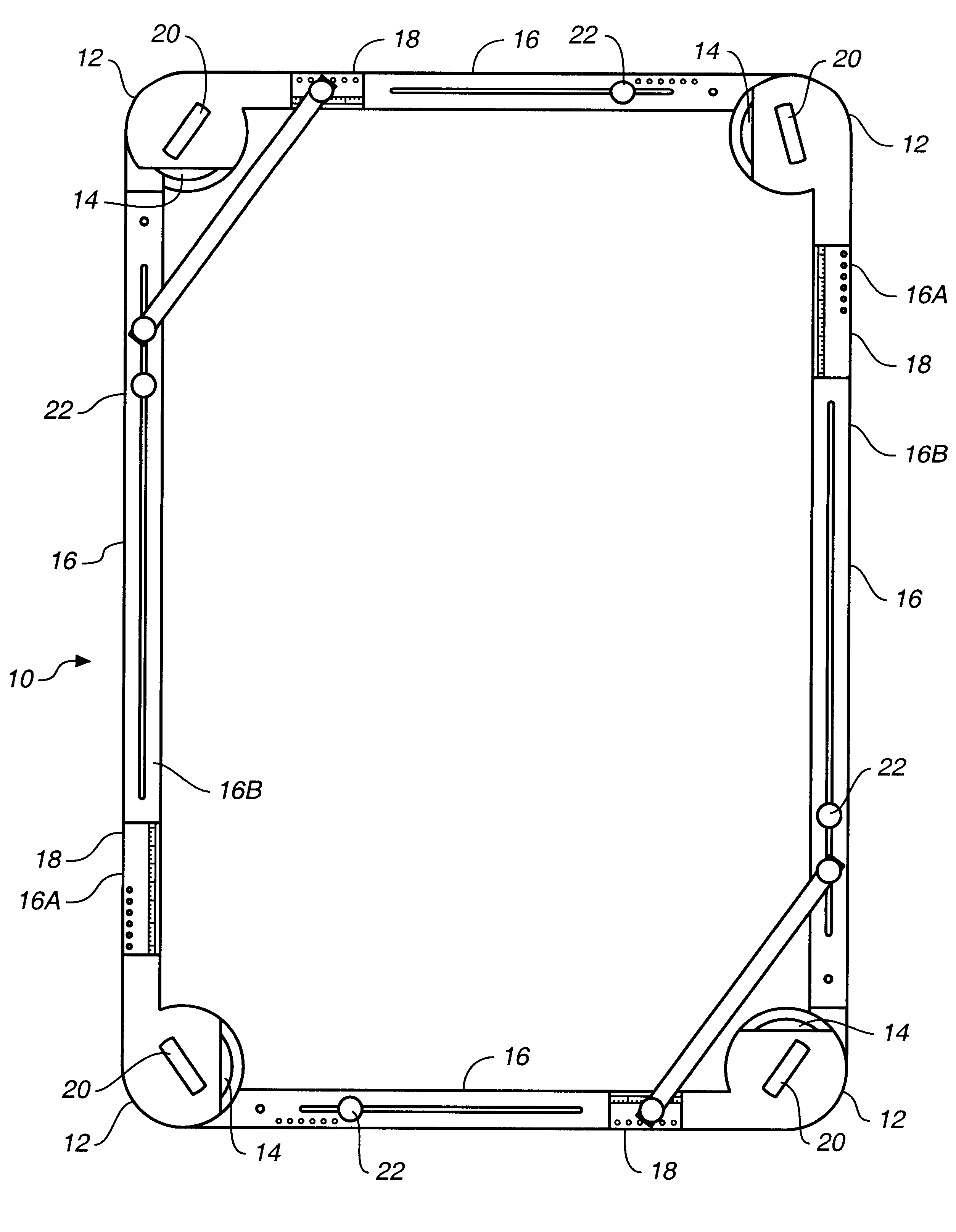
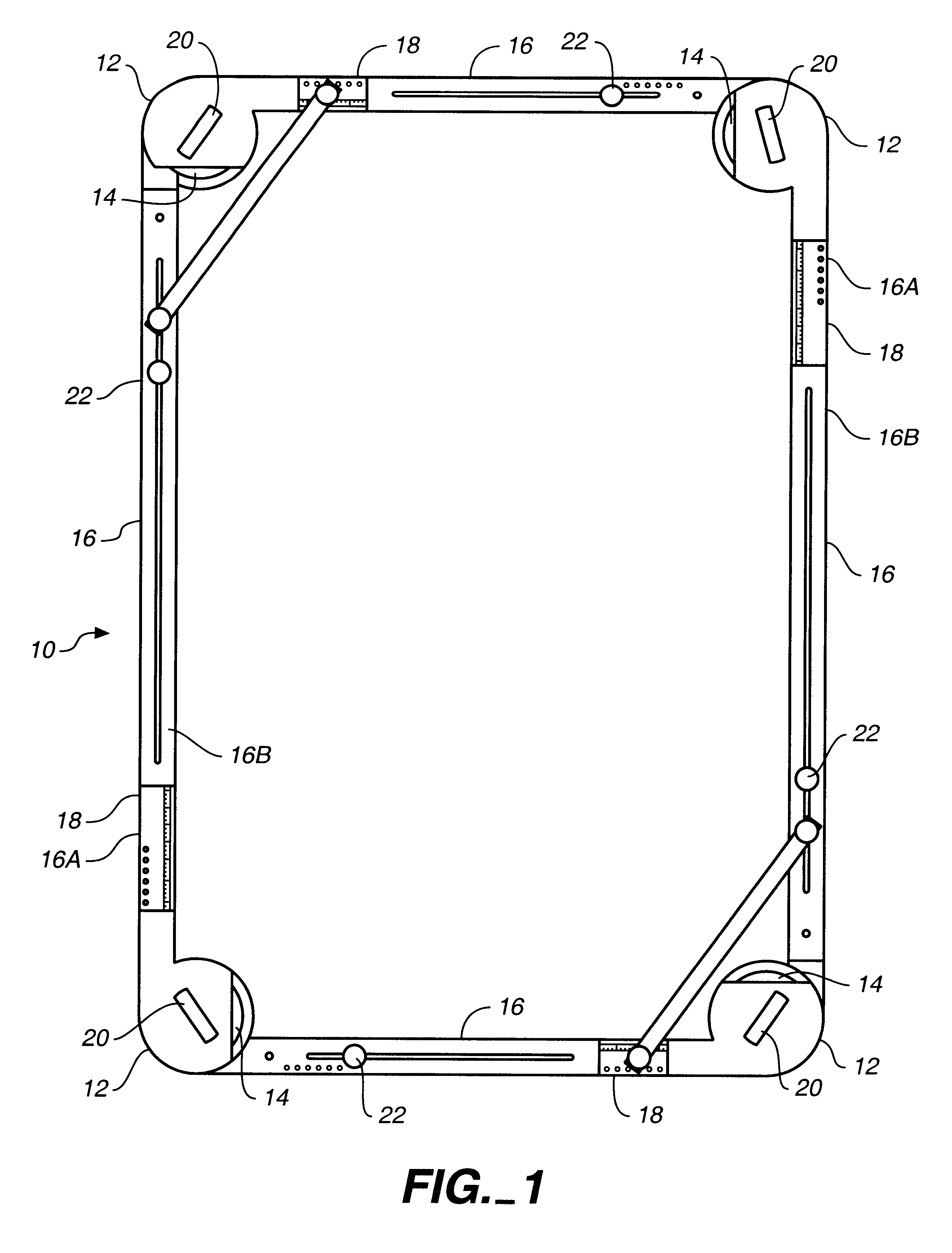
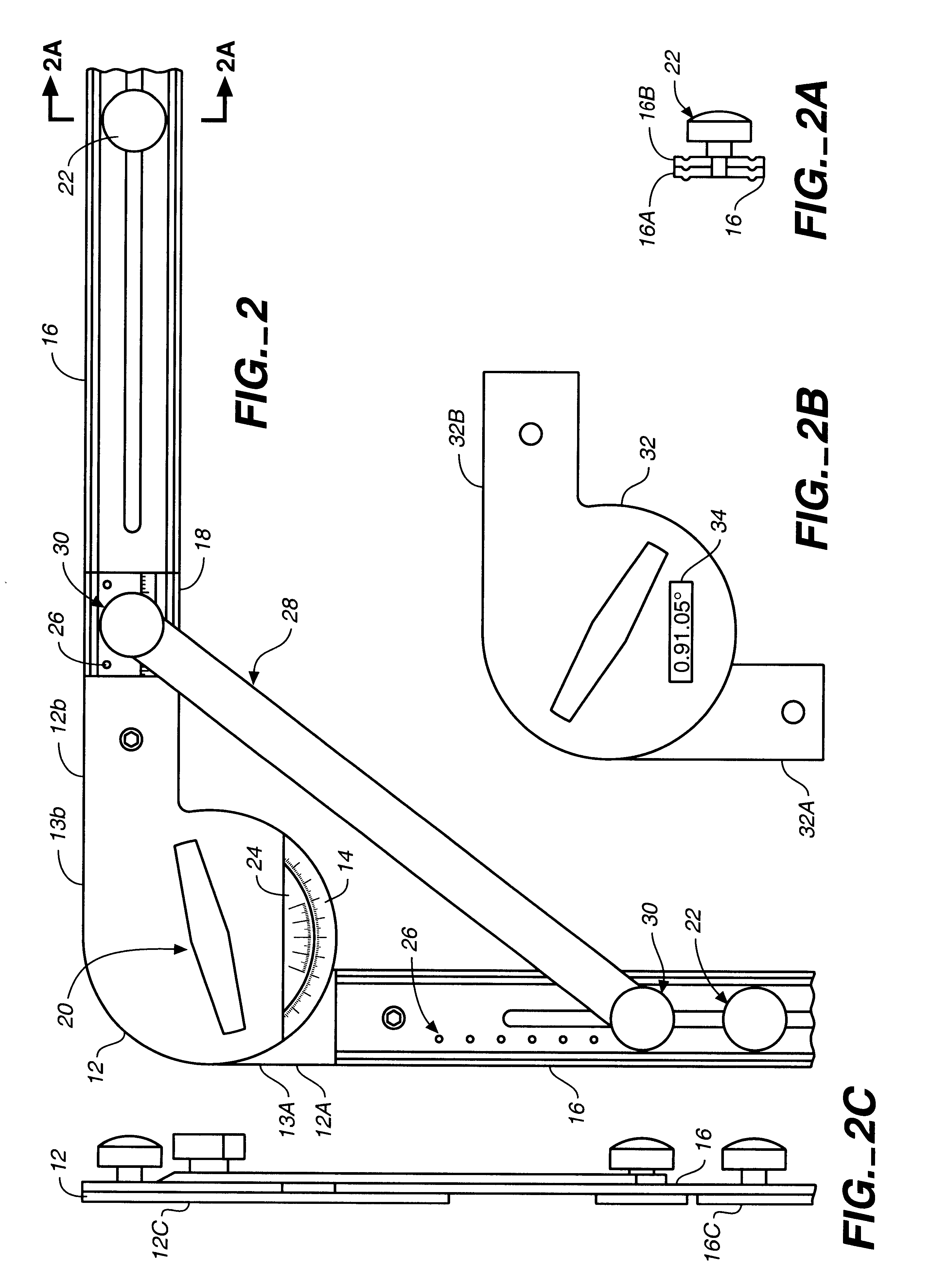
FIG. 1 is a plan view of a template maker 10 of this invention, illustrating a plurality of adjustable-angle corner members 12 each bearing an angle scale 14, connected to one another by a plurality of adjustable-length edge members 16 each including a length scale 18. Each corner member 12 is positioned at the ends of the adjoining adjustable-length edge members, so that the corner member can be placed into the true corner of the space being measured, without interference by the edge members. Each corner member 12 preferably includes a corner lock 20 (e.g., a knob on a threaded shaft) which enables free angular movement when loosened, but can be tightened to lock the corner member into a desired angularity when placed into position on a wall or other surface. Each edge member 16 similarly preferably includes a locking knob 22 which enables free extension and retraction of the respective segments of the edge member (described infra) when loosened, but can be tightened to lock the ed...


PUM


Abstract

A method for defining a regular or irregular shape utilizes a template apparatus including a plurality of radially-adjustable corner members connected by length-adjustable straight edge members. The corner members include an angle scale to display the defined angle, while the edge members include a length scale to display the defined length of that edge.

Description

1. Field of the InventionThis invention relates generally to tools and hardware, and more specifically to an improved method and apparatus for generating a template for applications in, inter alia, the glass, mirror, marble and countertop cutting, fitting and installation industries.2. Description of the Prior ArtSome construction situations involve fabrication and installation of a piece of material that is odd-sized, non-symmetrical, or otherwise irregular in shape, for example, the cutting and placement of a piece of glass into an irregular polygon window frame. One known method of defining the irregular shape is to construct a template of that shape, and later use that template to cut the glass. To make a template several methods have been used: a. A solid plywood sheet may be cut to the desired shape. b. Strips of plywood may be tacked or hot glued together to define the desired shape. c. A sheet of cardboard or paper may be cut out to the desired shape.In each example the phys...

Claims


Application Information

Patent Timeline
IPC IPC(8): E04F21/18
CPCE04F21/18E04F21/0076
Inventor KLASS, KEVIN M.MATTHEWS, III, WALTER I.
Owner KLASS KEVIN M
Learn More