Vacuum spittoon for collecting ink during servicing of ink jet printheads

a technology of ink jet printhead and vacuum spittoon, which is applied in printing and other directions, can solve the problems of releasing undesired ink aerosol, contaminating the printhead and the internal surface of the printing mechanism, and additional undesired problems

Inactive Publication Date: 2003-05-13
HEWLETT PACKARD DEV CO LP
View PDF17 Cites 14 Cited by
  • Summary
  • Abstract
  • Description
  • Claims
  • Application Information

AI Technical Summary

Problems solved by technology

As the printhead is firing ink droplets into the spittoon, it releases undesired ink aerosol.
These small droplets are often not deposited directly into the spittoon, but instead end up contaminating the printhead and the internal surfaces of the printing mechanism.
Ink contamination causes additional undesired problems such as dirt build-up, high frictional forces on moving parts, and operator exposure to wet ink.
This technique is not satisfactory, however, for inks that contain significant amounts of solids because the absorbent material can quickly clog.
The accumulated solids continue to build up until they contaminate the printhead.
The absorbent method also has limits for non-solid inks because a large volume of absorbent material must be provided to store the amount of ink discharged over the life of the printer.
This makes the printer larger, more expensive, and imposes other restraints on the design.
Spitting onto absorbent cloth causes a buildup of ejected liquid in the cloth, requiring a large volume of the cloth to be stored in the printer.
The service area of the printer becomes contaminated also.
Spitting onto a rotating wheel requires either a wheel of large diameter, badly affecting the form factor of the printer, or allowing a large distance from some areas of the print head face to the wheel, promoting aerosol that cross contaminates the printheads and the printer.
Spitting onto absorbent foam can cause a build up of ejected ink that can touch and contaminate the printheads as they pass over the spittoon.

Method used


Image

  • Vacuum spittoon for collecting ink during servicing of ink jet printheads
  • Vacuum spittoon for collecting ink during servicing of ink jet printheads
  • Vacuum spittoon for collecting ink during servicing of ink jet printheads

Examples


Embodiment Construction

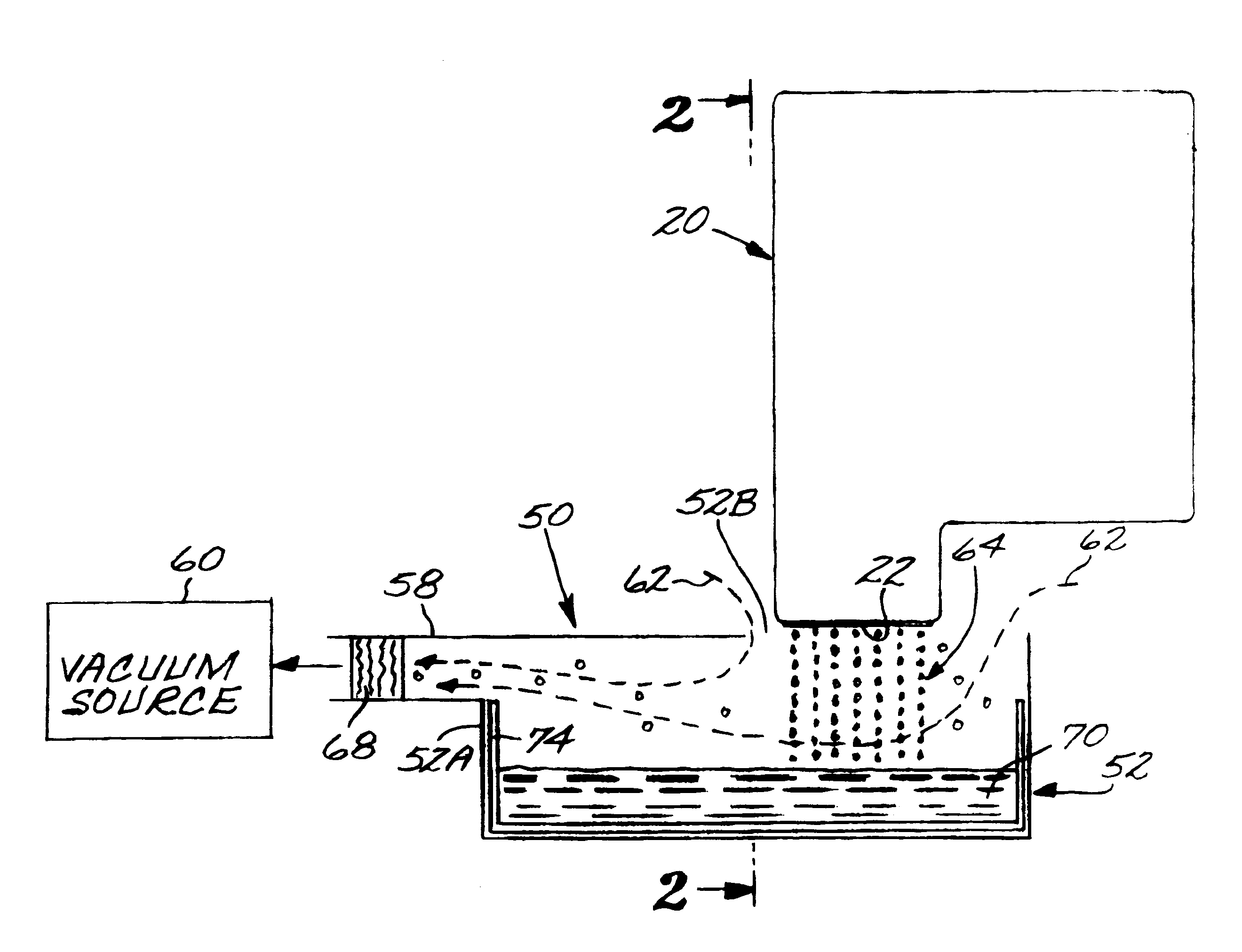
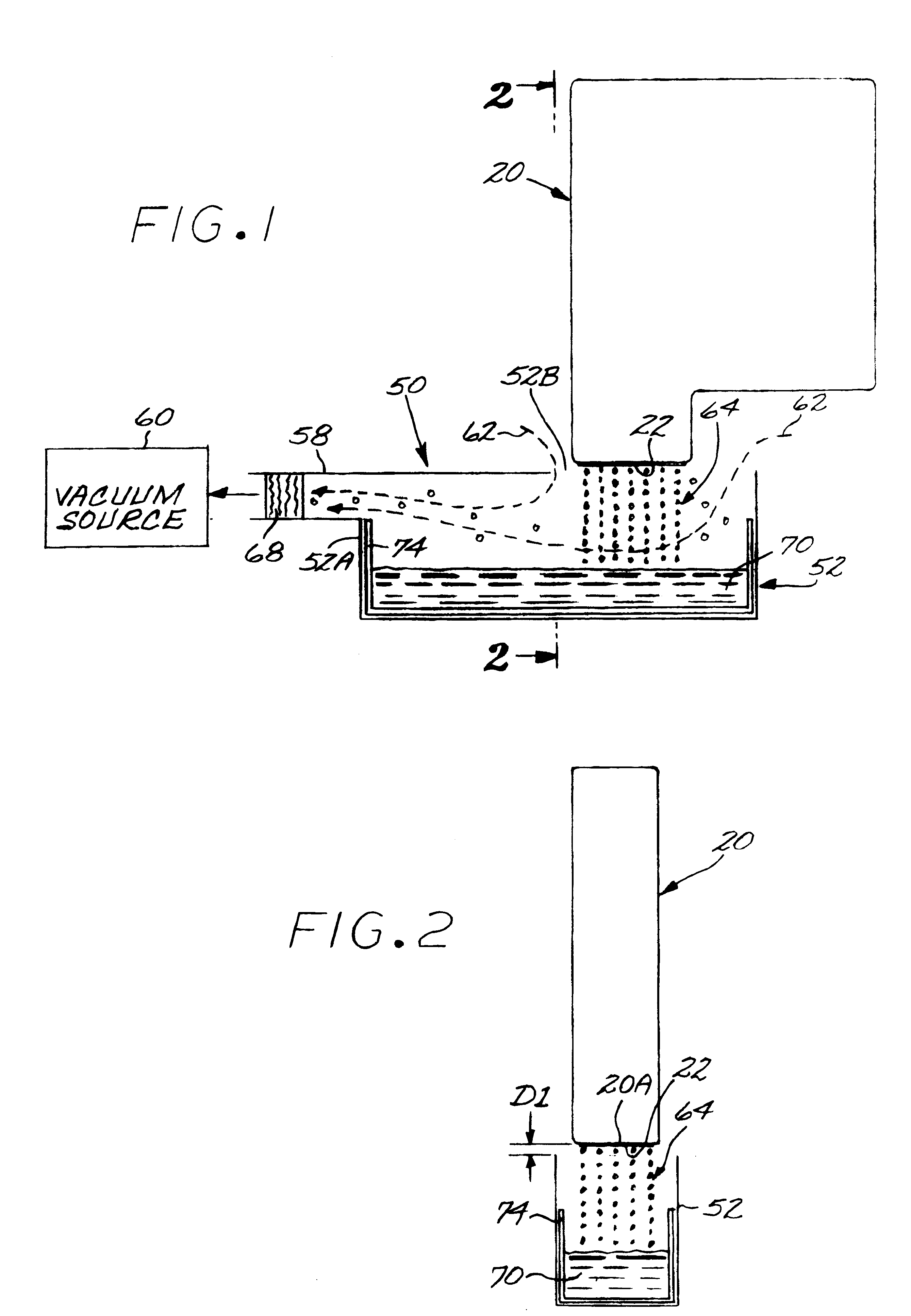
FIG. 1 shows a printhead 20 positioned at a service station 50 of a printing system. The printhead is positioned over a spittoon container 52 defining a chamber 54. A vacuum line 58 is fluidically coupled to the chamber 54, e.g. through a side or to the bottom of the chamber 54, and to a vacuum source 60. For this exemplary embodiment, the line 58 is connected to the side 52A of the container 52. Exemplary sources of the vacuum can include a fan system for producing a vacuum, or, in the event a vacuum system is already employed by the printing system, such as a vacuum media hold-down system, a tap off this vacuum system. A filter 68 is positioned in the line 58.

When positioned at the service station as shown in FIG. 1, and with the vacuum source 60 activated and producing an airflow indicated by arrows 62 into the chamber 54, the printhead can be actuated to spit droplets of ink from its nozzle array 22. The resulting droplets of ink and aerosol, indicated generally by reference 64,...


PUM


Abstract

A collection spittoon with a vacuum connection draws air and ink ejected during service spitting through an opening in the top of the spittoon. The collected ink includes main ejected drops and aerosol generated during the service process. A method for servicing an inkjet printhead comprises positioning the printhead over an opening in a spittoon chamber, establishing an air flow into the chamber through the opening, actuating the printhead to spit ink droplets in a service mode, and collecting the ink droplets and associated aerosol by drawing the ink droplets and aerosol into the chamber with the air flow.

Description

TECHNICAL FIELD OF THE DISCLOSUREThe invention relates to servicing of ink jet printheads.BACKGROUND OF THE DISCLOSUREAn inkjet printing mechanism is a type of non-impact printing device which forms characters and other images by controllably spraying drops of ink from a printhead. Inkjet printing mechanisms may be employed in a variety of devices, such as printers, plotters, scanners, facsimile machines, and the like. For convenience, inkjet printers are used herein to illustrate the concepts of the present invention.The printhead ejects ink through multiple nozzles in the form of drops which travel across a small air gap and land on a recording media. The drops are very small. Inkjet printers commonly print within a range of 180 to 600 dots per inch (dpi) or even higher. The ink drops dry on the recording media shortly after deposition to form the desired printed images.There are various types of inkjet printheads including, for example, thermal inkjet printheads and piezoelectric...

Claims


Application Information

Patent Timeline
Patent Type & Authority Patents(United States)
IPC IPC(8): B41J2/165
CPCB41J2/16508B41J2002/1742B41J2/1721
Inventor WEBSTER, GRANT A.RUTLAND, JEFFREY D.MURPHY, JOHN
Owner HEWLETT PACKARD DEV CO LP
Why Eureka
Try Eureka