Covering block for decreasing wave forces

a technology of wave force and cover block, which is applied in the direction of piers, groynes, artificial islands, etc., can solve the problems of ineffective dissipation and relief of wave force of most conventional blocks, and the size of the conventional block is too large to be conveniently installed

Inactive Publication Date: 2003-05-13
YANG WON HOI
View PDF11 Cites 12 Cited by
  • Summary
  • Abstract
  • Description
  • Claims
  • Application Information

AI Technical Summary

Problems solved by technology

Most of the conventional blocks, however, are ineffective for dissipating and relieving wave forces.
Further, they are too large to be conveniently installed.

Method used


Image

  • Covering block for decreasing wave forces
  • Covering block for decreasing wave forces
  • Covering block for decreasing wave forces

Examples


Embodiment Construction

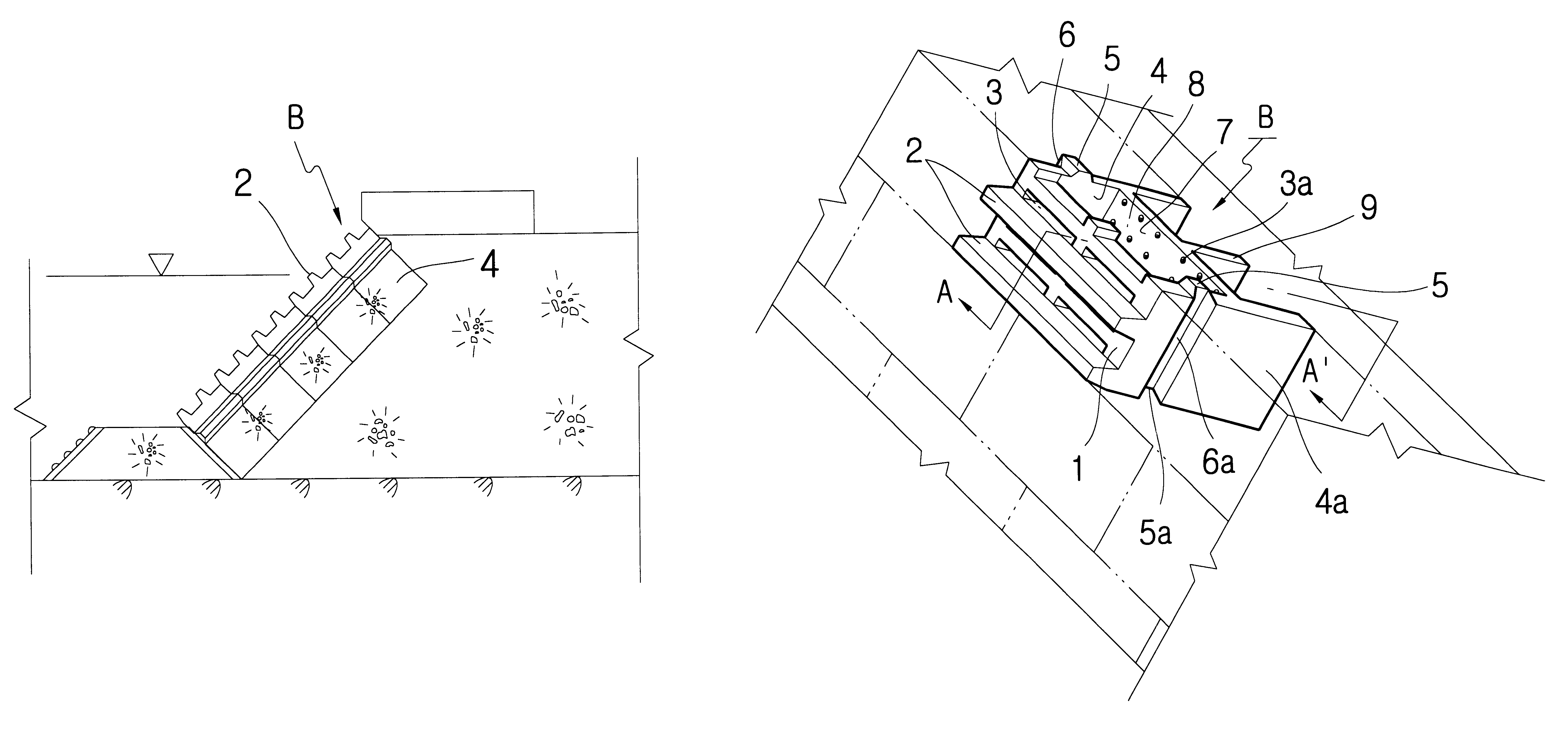
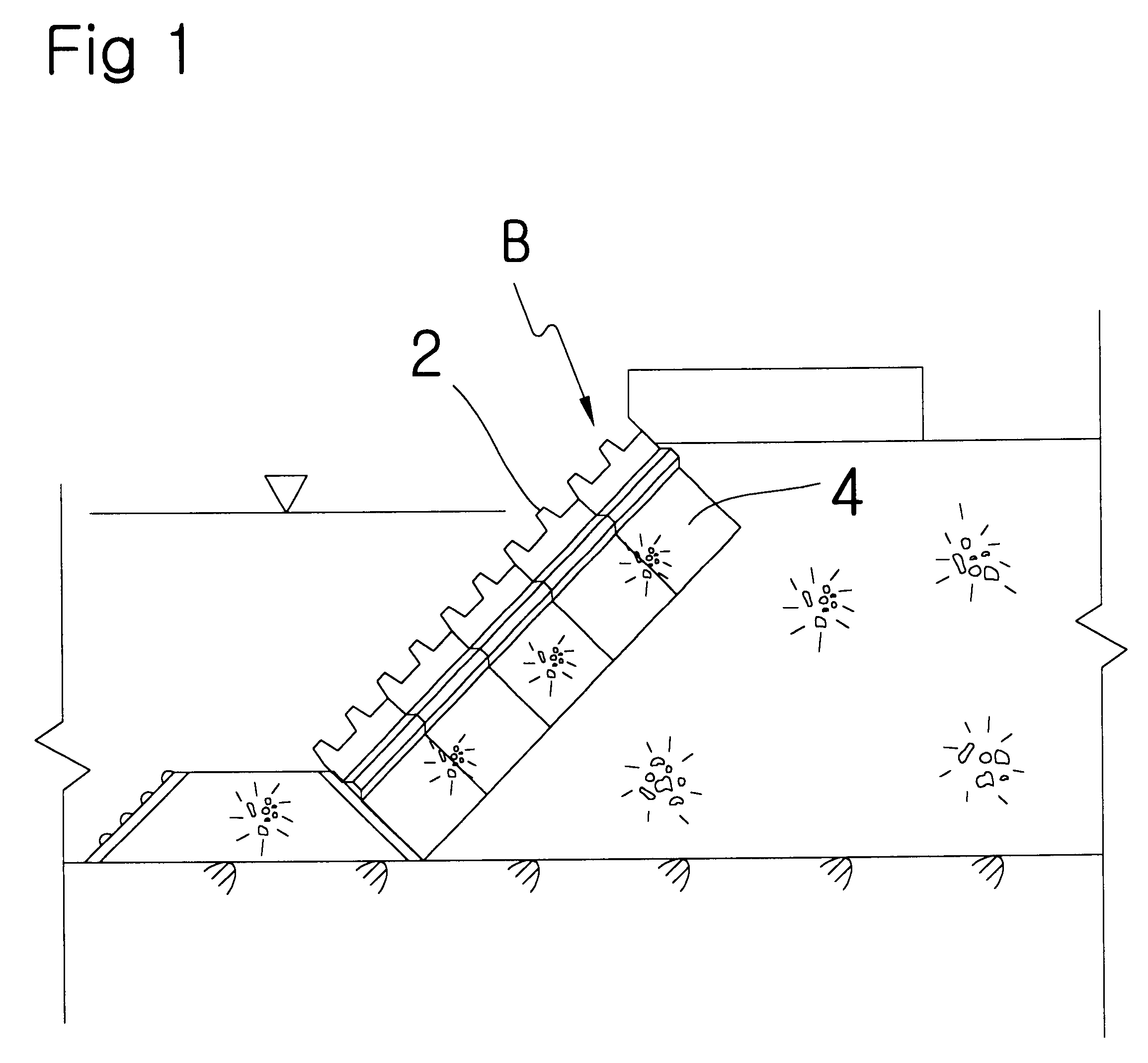
The blocks B of the present invention, which are to be installed on a breakwater as in FIG. 1, are usually set up and assembled one to another by cranes in a step by step manner, and finally arranged and fixed to the breakwater.

The construction of the blocks B, is hereinafter disclosed.

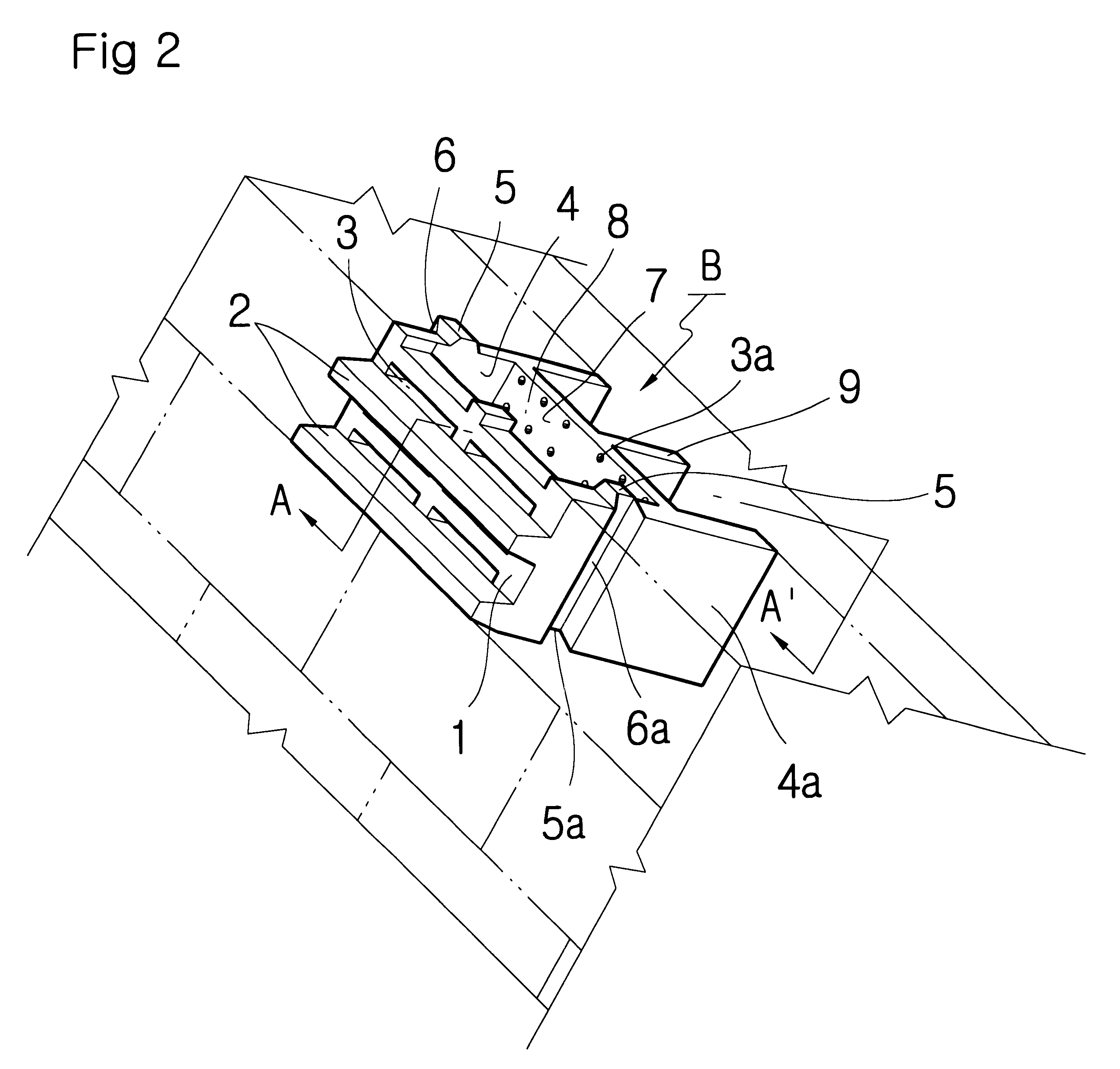
In the drawings, each block B of the present invention, comprises a front wall 1 on which are formed horizontal projections 2 that are disposed facing the sea. The front wall 1 also defines transversal holes 3 through which waves can pass through the front wall. Side walls 4, 4a are joined perpendicular to the front wall 1, at both sides thereof, and to a partition wall 7 which is integral with the side walls 4, 4a at both ends. An intermediate wall 9 extends rearward from a center portion of the partition wall 7. The side walls 4, 4a form upper protrusions 5 and lower recesses 5a on the upper and lower part thereof, and also form a side protrusion 6 vertically out of one side wall and a side recess 6...


PUM


Abstract

A block for constructing a breakwater comprises a front wall in which horizontal projections are formed with transverse rectangular-shaped holes therebetween. Side walls extend from both ends of the front wall. A partition wall in which multiple holes are formed to communicate with the transverse rectangular-shaped holes is jointed to the side walls at both ends and spaced from the front wall. A detention area is defined by the front wall, partition wall and side walls for receiving the overflow waves through the transverse rectangular-shaped holes in the front wall.

Description

This application claims priority to Korean Patent Application No. 2000-23605 filed Aug. 21, 2000.This invention relates to blocks to be assembled and used for constructing a breakwater that can decrease wave forces effectively.BACKGROUND OF INVENTIONIn the prior art, rubble mounds are used on inclined surfaces of a breakwater. Strong or impulse waves and tides easily remove these rubble mounds.Korean patent application No. 1999-46541 and Korean utility model application No. 1999-21409, filed in the name of the same inventor, show blocks for constructing a breakwater having horizontal holes smaller in size than rubble in the mound. The blocks include a large number of holes. The large number of holes prevents loss of rubble from the mounds. The large number of holes effectively decreases the power of waves between projections in the blocks, particularly for overriding large waves that hinder the serenity of the inner sea.Most of the conventional blocks, however, are ineffective for d...

Claims


Application Information

Patent Timeline
Patent Type & Authority Patents(United States)
IPC IPC(8): E02B3/06E02B3/12E02B3/14
CPCE02B3/129E02B3/06Y02A10/11E02B3/14
Inventor YANG, WON-HOI
Owner YANG WON HOI
Why Eureka
Try Eureka