Anchoring device for fixing a structural cable to a building element

a technology for fixing devices and structural cables, which is applied in the direction of bridges, rod connections, manufacturing tools, etc., can solve the problems of significant and expensive maintenance operations of anchoring devices such as these, and the operator is not accessibl

Inactive Publication Date: 2003-06-17
COBRA CABLE TIE +1
View PDF16 Cites 46 Cited by
  • Summary
  • Abstract
  • Description
  • Claims
  • Application Information

AI Technical Summary

Problems solved by technology

However, the ends of the threaded rods screwed into the outer plate are located on the same side as the cables and are therefore not accessible to the operator unless he dismantles the entire anchoring device.
An anchoring device such as this therefore involves significant and expensive maintenance operations because the mechanically stressed parts are located in places which are difficult to access.

Method used


Image

  • Anchoring device for fixing a structural cable to a building element
  • Anchoring device for fixing a structural cable to a building element
  • Anchoring device for fixing a structural cable to a building element

Examples


first embodiment

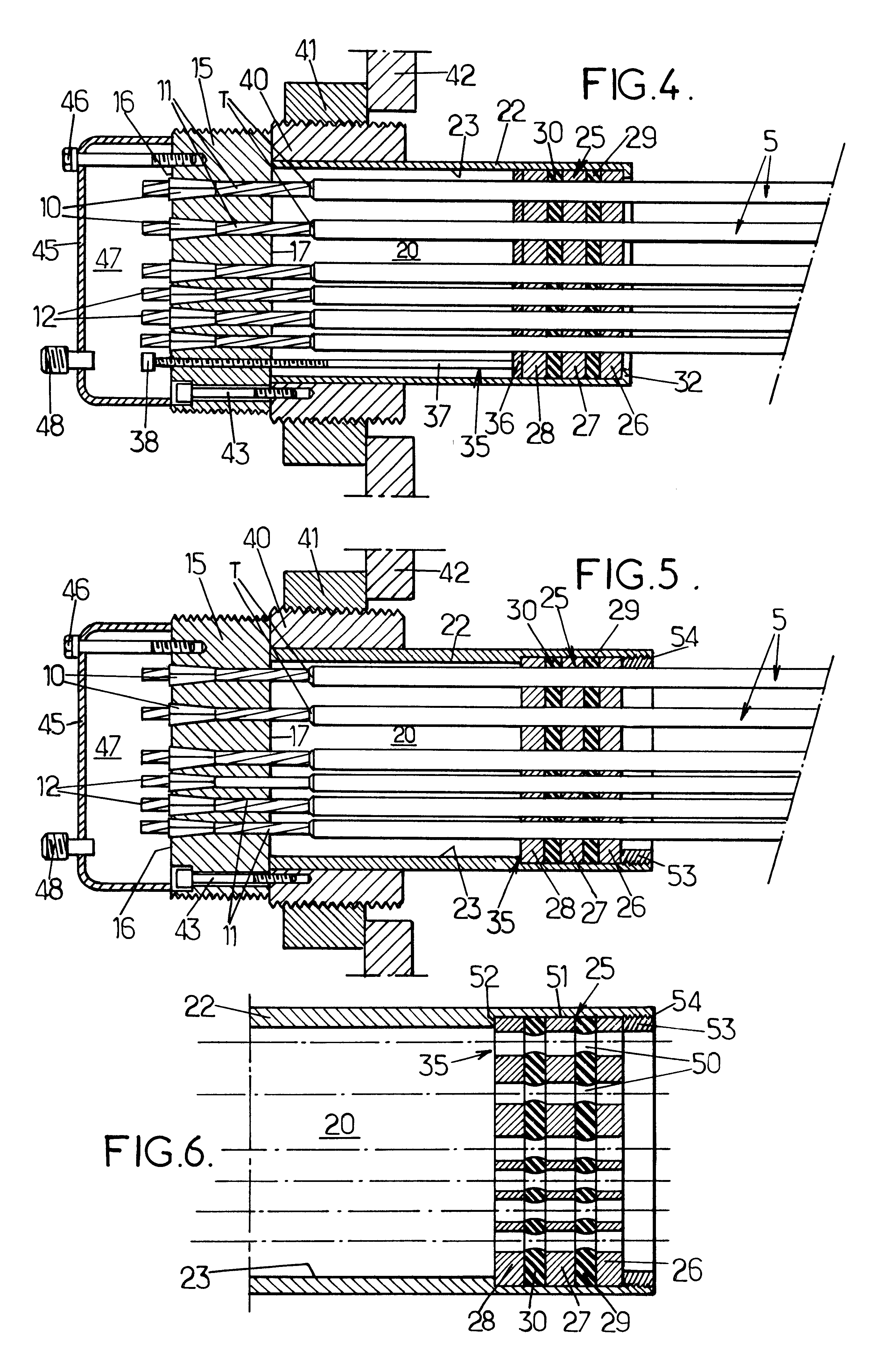
In the first embodiment depicted in FIG. 4, the bearing means 35 consist in an insert plate 36 which is perforated and pressed against the inner plate 28 and in threaded rods 37 (just one being depicted in FIG. 4). The threaded rods adopt the shape of screws each equipped with a head 38.

A first end of the threaded rod or screw 37 presses against the insert plate 36 while the second end of the rod 37 passes through a tapped hole 12 formed in the perforated block 15 so that the head 38 projects from the outer face 16 of this block. The threaded rod 37 can be operated by means of the head 38 to be screwed through the tapped hole.

The insert plate 36 is pushed back by the screwing of the threaded rods or screws 37. During this compression, the insert plate 36 moves the inner plate 28 closer to the outer plate 26 which itself remains stationary.

In order to immobilize the perforated block 15 with respect to the anchoring block 9, an adjusting tube 40 is mounted secured to the outer face of...

second embodiment

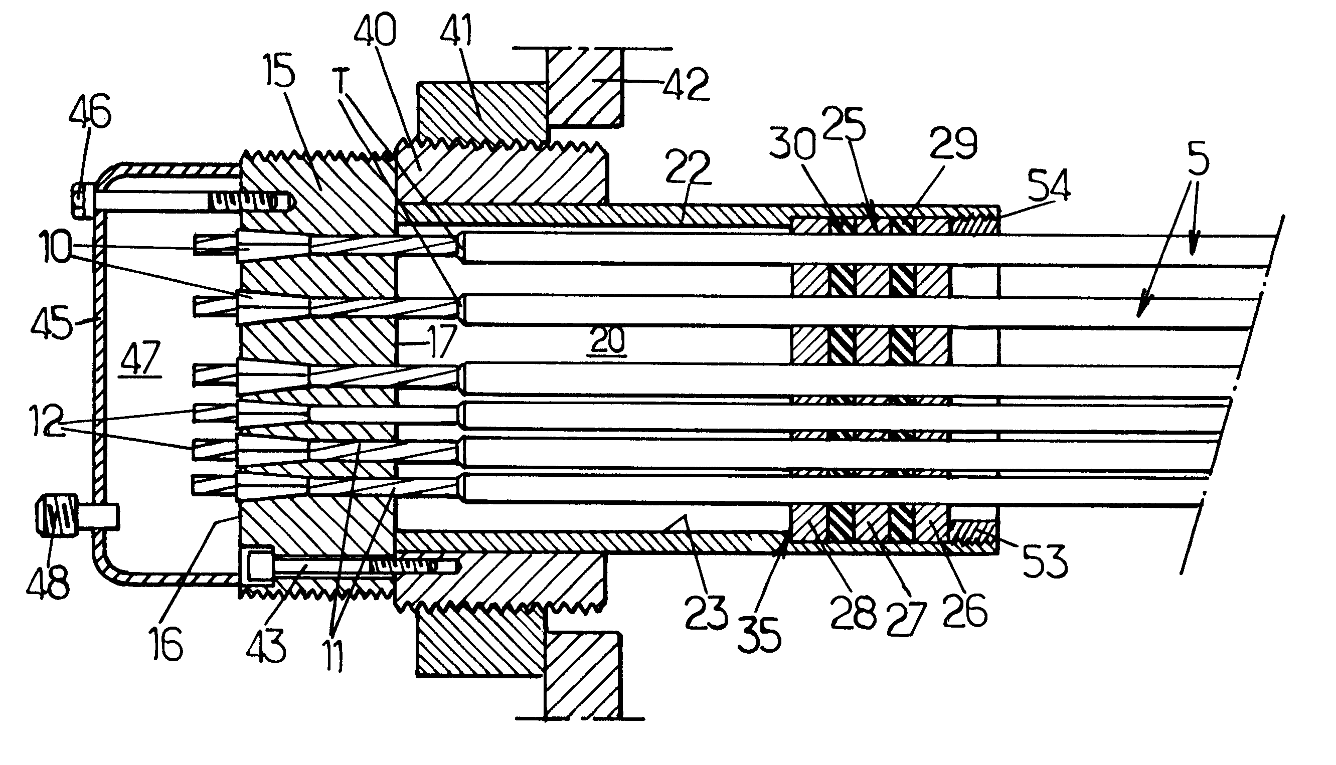
The second embodiment depicted in FIGS. 5 and 6 differs from the previous embodiment only in the form of the bearing means 35, the diameter of the passages formed in the pieces of packing 29 and 30, and the opposite end of the tube to the anchoring block.

The strands 5 are inserted in the pieces of packing 29 and 30 through passages 50 which have a diameter slightly smaller than that of the sheath 7 of the strands 5. In addition, a groove 51 is formed at the opposite end of the tube 22 to the anchoring block 15. The tube 22 thus has, at its end, a portion of inside diameter greater than the inside diameter of the rest of the tube. A step 52 is defined by this change in diameter. The three perforated plates 26 to 28 and the pieces of packing 29 and 30 are inserted in this groove 51 via the end of the tube 22. The plates and the pieces of packing are in abutment against the step 52 and are kept in compression against one another by means of a stop sleeve 53. This sleeve is attached to ...


PUM

PropertyMeasurementUnit
thicknessaaaaaaaaaa
diameteraaaaaaaaaa
tensionaaaaaaaaaa

Abstract

An anchoring device for fixing a structural cable to a building element, the cable comprising a plurality of strands each comprising wires which are themselves enclosed together in a protective sheath, each of the protective sheaths being interrupted at a terminal edge such that the strands have each an exposed end section. The exposed section is inserted in a sealed chamber with a packing box whereof on plate is fixed and the other plate is compressed by threaded rods.

Description

The present invention relates to anchoring devices for fixing structural cables to building elements.In particular, the invention applies each time it is necessary to fix a cable, subjected to tensile loadings, to equip building elements such as cable-stayed bridges, suspension bridges or the like, by connecting the tops of the towers of these bridges to their decks and to their anchor blocks.DESCRIPTION OF THE RELATED ARTThe cables habitually encountered in such building elements comprise a number of strands each of which comprises metal wires themselves enveloped together in a protective sheath, each of these protective sheaths being interrupted at a terminal edge so that the strands each have a bared end portion.The anchoring devices habitually encountered, particularly in EP-A-0 323 285, comprise:a perforated block in which the bared end portions of the various strands are individually anchored,a bearing surface which is secured to the building element and against which the peri...

Claims


Application Information

Patent Timeline
Patent Type & Authority Patents(United States)
IPC IPC(8): E01D19/14E01D19/00E04C5/12E01D11/02E01D11/00E01D11/04E01D19/16E04B1/34
CPCE01D19/14E04C5/122Y10T29/49874Y10T24/3909Y10T403/7051Y10T403/7062E04C5/12
Inventor STUBLER, JEROMELADRET, PATRICKPERCHERON, JEAN-CLAUDE
Owner COBRA CABLE TIE
Why Eureka
Try Eureka