
Staple gun

a technology of staple gun and stapling rod, which is applied in the field of staple gun, can solve the problems of staples being subjected to force, staples may jam, and staples may start to rattl

Inactive Publication Date: 2003-07-29
MAX CO LTD
View PDF2 Cites 18 Cited by
  • Summary
  • Abstract
  • Description
  • Claims
  • Application Information

AI Technical Summary

Benefits of technology

This design effectively suppresses cover plate rattling and maintains a stable staple injection orbit, reducing the likelihood of staple jams by ensuring the cover plate remains firmly fixed, even under forces from the staple driver and target object hardness.

Problems solved by technology

However, such a staple gun has a problem that when a staple is injected from the staple injection nozzle 1, a staple may be subjected to a force caused by shock of the staple driver or hardness of a target object, the force tending to open, i.e., remove the cover plate 4 from the nozzle body 2.
Thus, the cover plate 4 begins to rattle, changing a staple injection orbit, which in turn easily causes a staple jam.

Method used


Image

  • Staple gun
  • Staple gun
  • Staple gun

Examples


Embodiment Construction

Description will now be directed to a staple gun according to an embodiment of the present invention with reference to the attached drawings.

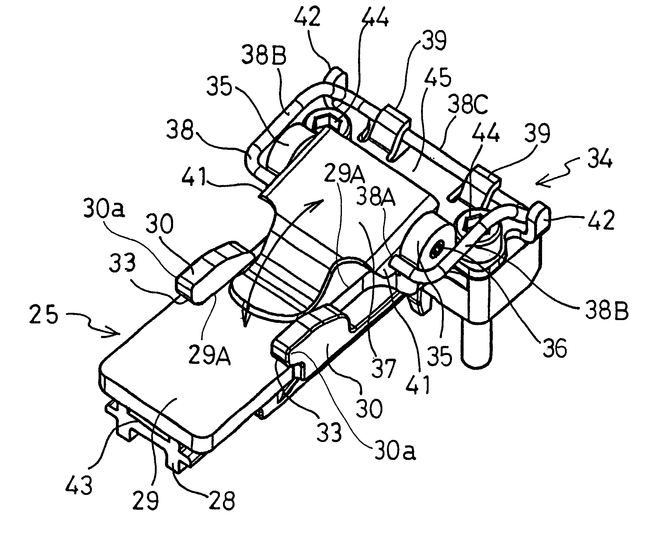
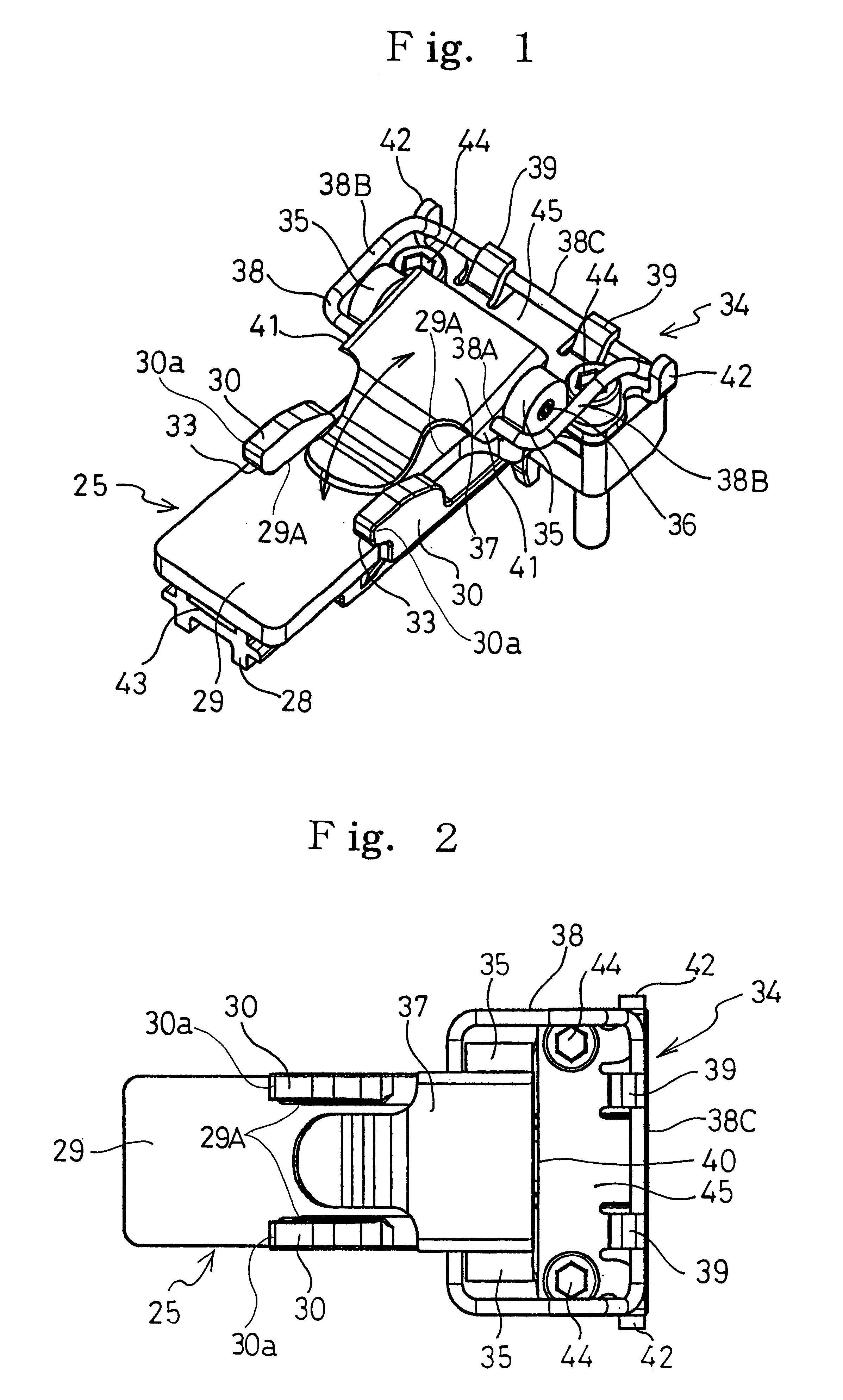
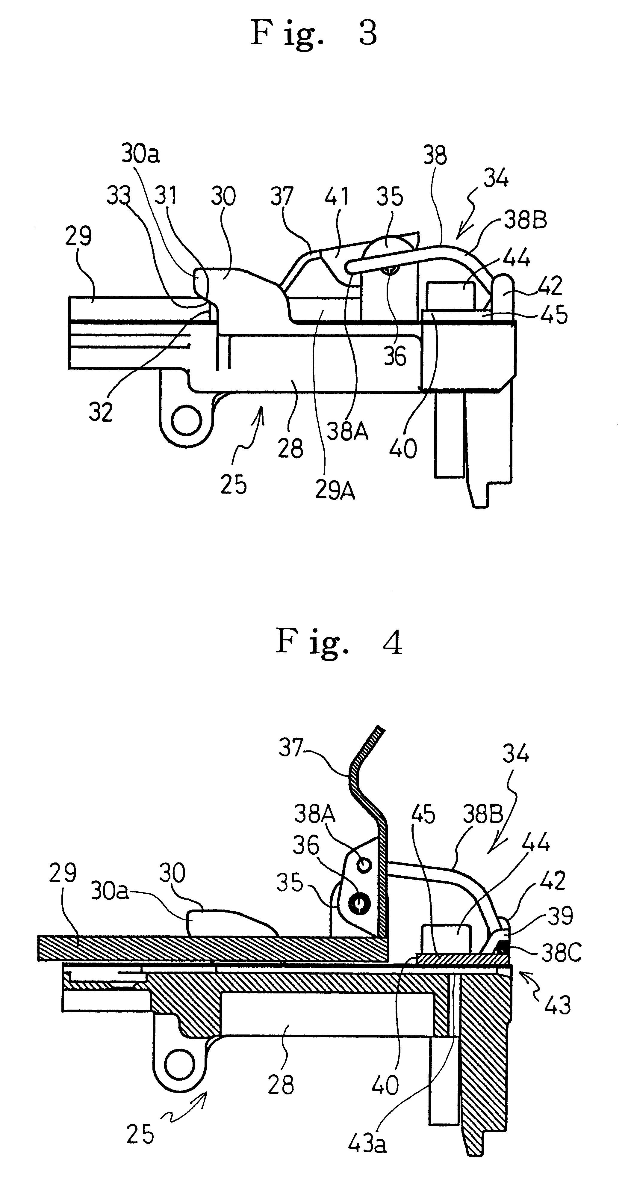
FIG. 7 shows a staple gun 20. The staple gun 20 includes: a staple gun main body 15; a handle 21 arranged below the staple gun main body 15; a trigger 22 arranged at left of the handle 21; and a staple injection nozzle 25 protruding forward from the left end of the staple gun main body 15. The staple gun main body 15 has a cylinder block 24 and a cylinder head 23.

A coupler 26 is arranged below the handle 21 of the staple gun 20. The coupler 26 is connected to a coupler (not depicted) of a compressed air supply hose (not depicted). Compressed air supplied from the coupler 26 is introduced to the cylinder head 23 through the interior of the handle 21 when the trigger 22 is pulled. Thus, the compressed air is supplied to the cylinder block 24. The cylinder block 24 has a built-in piston (not depicted). A staple driver is fixed to this piston. The ...


PUM


Abstract

A staple gun comprising a main body and a staple injection nozzle for injecting a staple into a target object, the staple injection nozzle including a nozzle body mounted on a staple striking body and a cover plate for removably closing an upper portion of a staple injection path of the nozzle body so as to guide the staple. The nozzle body has protrusions to receive an end portion of the cover plate and press this cover plate from upward, and an urging member is provided to urge the cover plate in a direction that the end portion of the cover plate intrudes into the protrusions.

Description

1. Field of the InventionThe present invention relates to a staple gun and in particular to a staple gun.2. Description of the Prior ArtConventionally, there are known staple guns such as those using electric power or compressed air to inject a staple into a target object.FIG. 8 shows a staple injection nozzle 1 for injecting a staple from a staple gun into a target object. This staple injection nozzle 1 has a nozzle body 2 protruding from the front portion of the staple gun. In this nozzle body 2, a staple injection path 3 is formed through which the stable is injected. The staple (not depicted) has a pair of pins to be struck into a target object and a linking portion connecting these pins. The pins are set in the staple injection path 3 in such a manner that the pins are directed toward the target object. The staple set in the staple injection path 3 is pushed forward from the rear end thereof by a staple driver.The staple injection path 3 has an upper portion closed by a cover p...

Claims


Application Information

Patent Timeline
Patent Type & Authority Patents(United States)
IPC IPC(8): B25C1/00B25C5/00B25C5/16B27F7/34B25C5/06B25C5/13
CPCB25C1/005B25C5/1665
Inventor ADACHI, MICHIAKIKOSUGE, MAKOTOICHIBA, TOMOFUMI
Owner MAX CO LTD
Learn More