Golf swing frequency analyzer

a frequency analyzer and golf swing technology, applied in the field of golf devices, can solve the problems of shaft from the rest axis, unsatisfactory drive, club head striking face not properly angled relative to the ball,

Inactive Publication Date: 2003-08-19
PERFECTED FALCON JOINT VENTURE
View PDF21 Cites 115 Cited by
  • Summary
  • Abstract
  • Description
  • Claims
  • Application Information

AI Technical Summary

Problems solved by technology

If the ball is struck when the shaft is bent, the club head's striking face is not properly angled relative to the ball.
A misaligned striking face results in an unsatisfactory drive, and therefore it is preferred that a club shaft be straight when the striking face and ball meet.
However, this phenomenon is not considered here as part of the ball striking mechanism due to its unpredictability and unquantifiability.
The force due t

Method used


Image

  • Golf swing frequency analyzer
  • Golf swing frequency analyzer
  • Golf swing frequency analyzer

Examples


Embodiment Construction

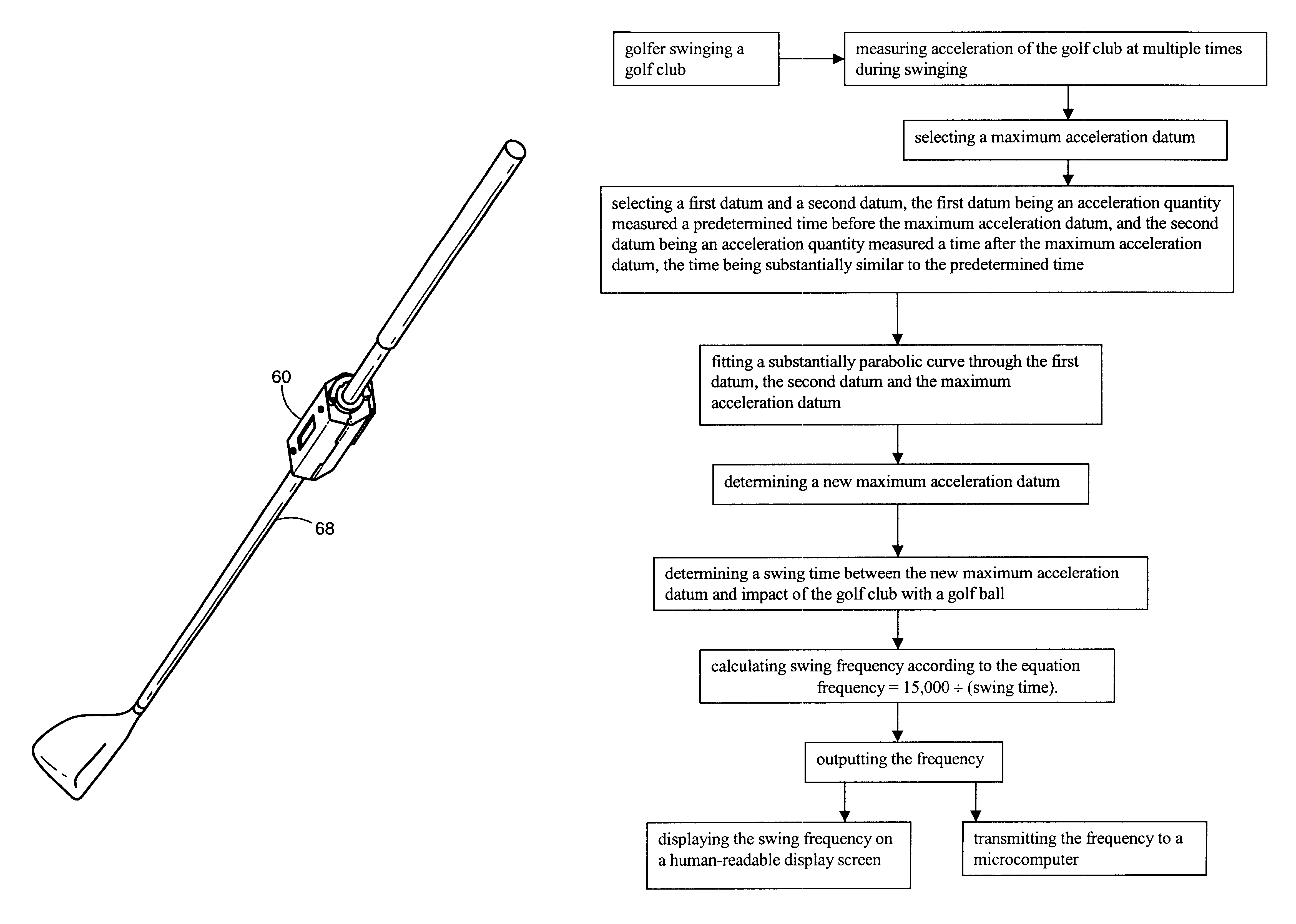
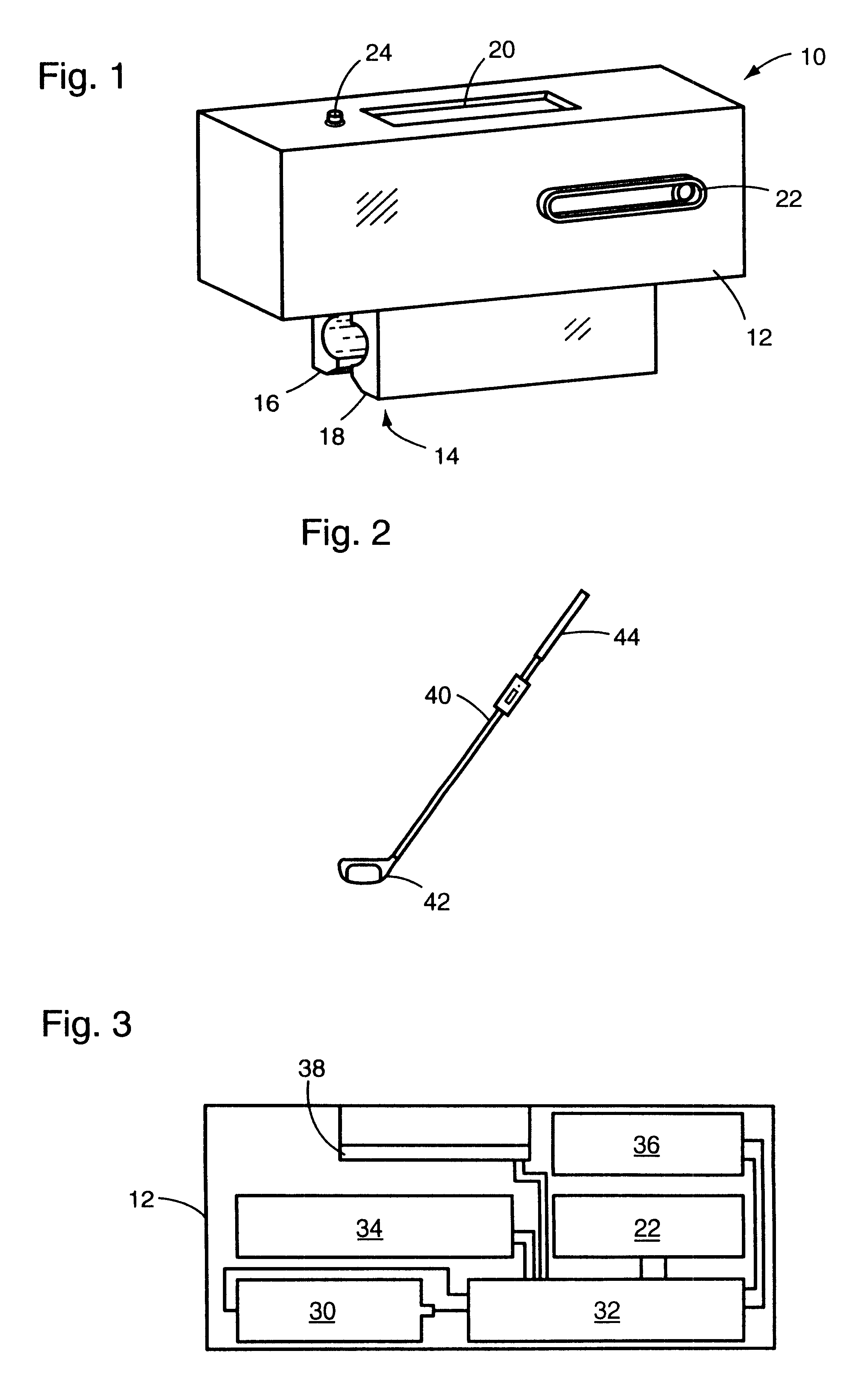
The analyzer 10, shown in FIG. 1, has an elongated parallelepiped housing 12. The housing is preferably made of a polymer, and has an internal chamber (shown schematically in FIG. 3) which houses electronic components. A shaft mount 14, preferably a clamp having a pair of opposed lips 16 and 18, is mounted to the underside of the housing 12, preferably integrally with the housing 12. The opposed lips are positioned on opposite sides of a golf club shaft in the operable position, clampingly gripping the shaft between the lips as shown in FIG. 2. Of course, many other structures are contemplated as adequate substitutions for the preferred shaft mount for attaching the analyzer to a golf club shaft. Spring-biased clamps, screws, double-sided tape, pipe clamps or tape wrapped around the shaft and housing 12, etc. could all be substituted for the shaft mount 14.

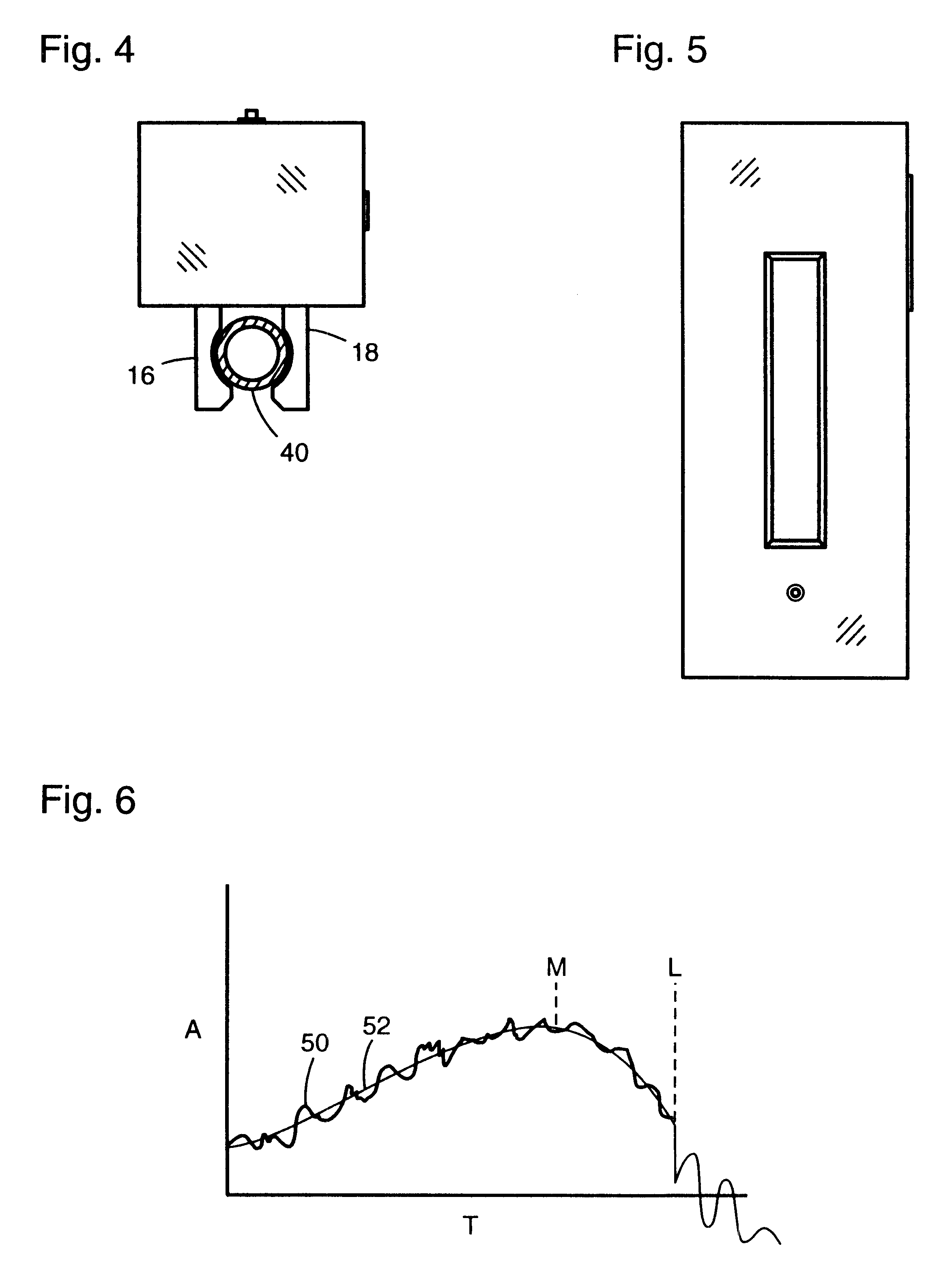
The display screen 20 is mounted in the upper wall of the housing 12 for displaying an output. The screen 20 is preferably a liq...


PUM


Abstract

A golf swing analyzer that can be attached to a golf club shaft. The analyzer includes a housing with an integral shaft mount. The housing contains an internal chamber in which an accelerometer, microprocessor and data storage are contained, and an output display screen mounted to the housing. The analyzer measures acceleration during a golfer's swing and calculates the frequency of a club that would be straight at ball impact.

Description

1. Field of the InventionThe invention relates to golf devices, and more specifically to a device for measuring the acceleration of a golfer's swing for the purpose of matching a golf club having a desired frequency of oscillation to the golfer's swing.2. Description of the Related ArtA golf club is a flexible rod which, when driven toward a ball by the golfer's hands, bends like a spring under the force applied to it. As the club head advances rapidly toward the ball, the shaft straightens. At some point in the swing, the striking face of the club head strikes the ball.Striking faces are designed to strike a ball when the club's shaft is straight, imparting the desired loft to the ball due to the angle of the striking face at impact. If the ball is struck when the shaft is bent, the club head's striking face is not properly angled relative to the ball. A misaligned striking face results in an unsatisfactory drive, and therefore it is preferred that a club shaft be straight when the...

Claims


Application Information

Patent Timeline
IPC IPC(8): A63B59/00A63B69/36A63B24/00A63B53/00G01P15/00
CPCA63B59/0074A63B69/3632A63B71/0622A63B2053/005A63B2059/0003A63B2220/40A63B2220/62A63B2220/64A63B2220/833A63B2225/50A63B60/42A63B53/005A63B60/002
Inventor HACKMAN, LLOYD E.
Owner PERFECTED FALCON JOINT VENTURE
Why Eureka
Try Eureka