Switching apparatus

a technology of switching apparatus and switch body, which is applied in the direction of switch power arrangement, air-break switch, high-tension/heavy-dress switch, etc., can solve the problems of limiting affecting the speed of operation, and affecting the ability of the switch to cope with the demands of increasing speed and control modifications

Inactive Publication Date: 2003-08-26
MITSUBISHI ELECTRIC CORP
View PDF8 Cites 6 Cited by
  • Summary
  • Abstract
  • Description
  • Claims
  • Application Information

AI Technical Summary

Problems solved by technology

However, due to the impact between coils caused by this high speed operation, a large impact force is generated by the movable coil and the fixed coils, and this device has the problem that the securing portions of the coils may be damaged.
In addition, in the device of FIGS. 24A and 24B, a single movable coil is used to perform both contact opening and contact closing, and there is a limit on the speed of operation when a driving force is provided only by an electromagnetic repulsive force, so the illustrated device has the problems that it is difficult for it to cope with demands for increased speed and control modifications.

Method used


Image

  • Switching apparatus
  • Switching apparatus
  • Switching apparatus

Examples


first embodiment

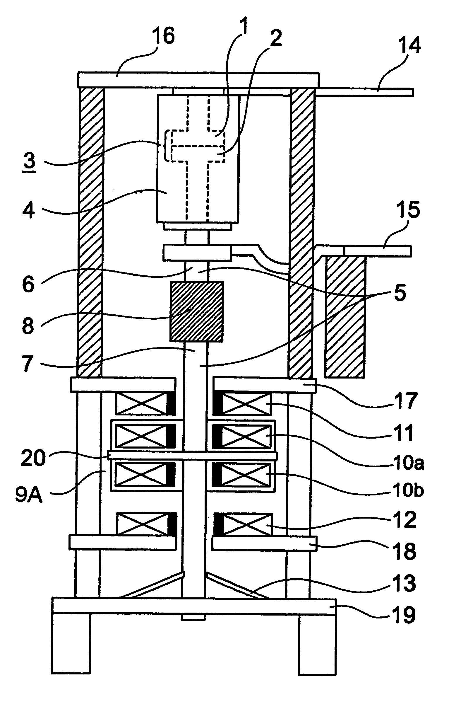
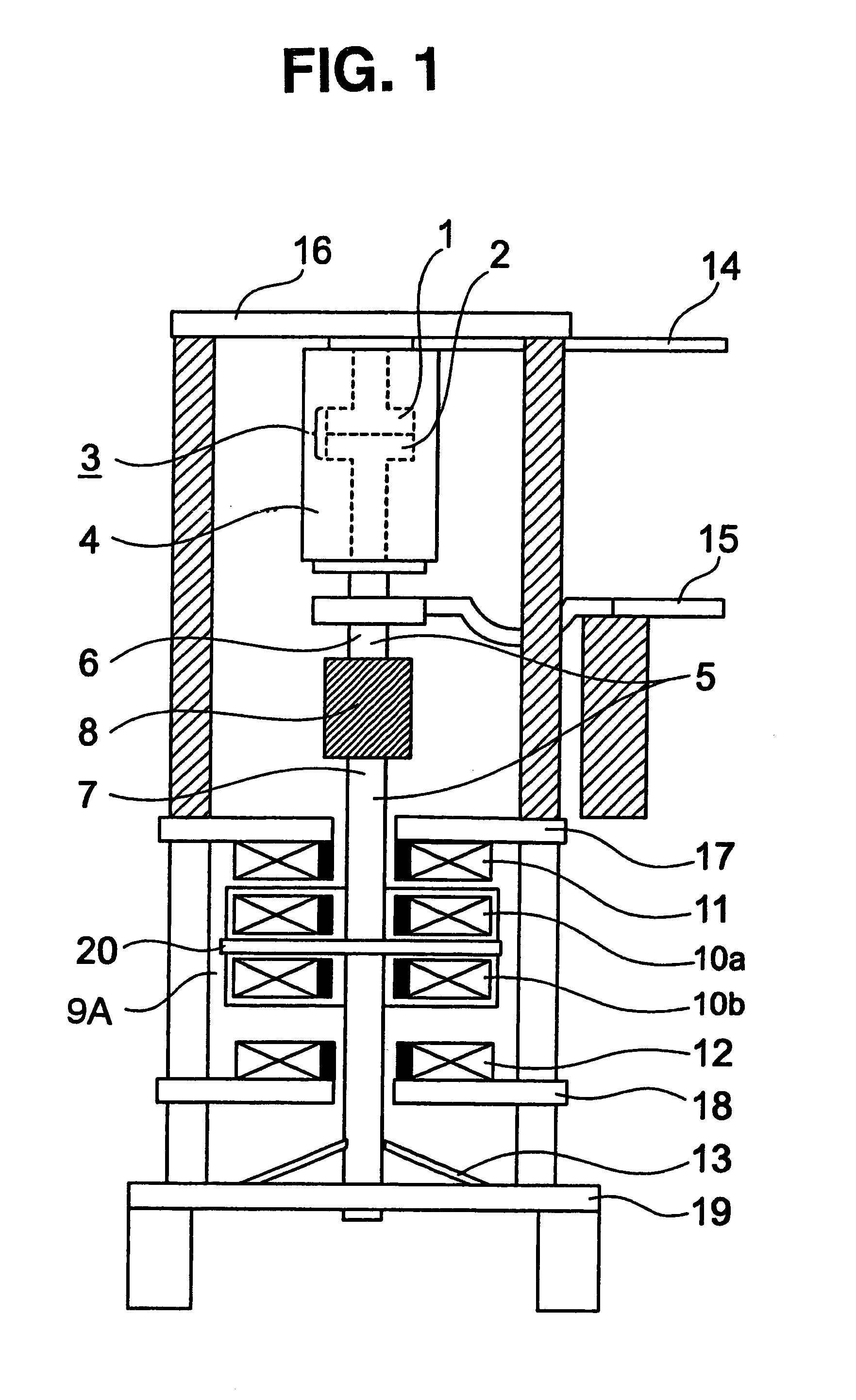
FIG. 1 is a schematic elevation of a switching apparatus according to the present invention. Like the apparatus shown in FIGS. 24A and 24B, this embodiment includes a switch portion 3 having a fixed electrode 1 and a movable electrode 2 housed inside an evacuated chamber 4. The fixed electrode 1 is secured to a support plate 16 which forms an outer plate of the switching apparatus. The movable electrode 2 opposes the fixed electrode 1 and can reciprocate with respect to the fixed electrode 1 between an open and a closed position. The fixed electrode 1 and the movable electrode 2 are respectively connected to a first terminal 14 and a second terminal 15 by which the switch portion 3 can be connected to an electric circuit. A movable shaft 5 having a live portion 6 and a non-live portion 7 connected to each other by an insulating rod 8 is connected to the movable electrode 2 and an operating mechanism 9A for opening and closing the switch portion 3. A support plate 20 perpendicular to...

third embodiment

FIG. 7 is a schematic elevation of an operating mechanism 9C of a switching apparatus according to the present invention. In FIG. 7, contact opening fixed coil 11 and contact closing fixed coil 12 are disposed back to back and secured to opposite sides of support plate 20. The fixed coils 11 and 12 and the support plate 20 are secured to an outer frame 51 of the switching apparatus. The fixed coils 11 and 12 are disposed between the movable coils 10a and 10b, with contact opening fixed coil 11 opposing contact opening movable coil 10a and with contact closing fixed coil 12 opposing contact closing movable coil 10b. The movable coils 10a and 10b are both secured to the movable shaft 5 so as to move together with the movable shaft 5 as it translates in its axial direction. The structure of the switching apparatus is otherwise the same as that of the embodiment of FIG. 1. The operating mechanism 9C is controlled by a control circuit having a structure like that of the control circuit 4...

fourth embodiment

FIGS. 8A and 8B are schematic elevations of an operating mechanism 9D of a switching apparatus according to the present invention showing the direction of current flowing in each coil of the operating mechanism 9D during contact opening operation and contact closing operation, respectively. FIG. 9 is a circuit diagram of a control circuit 60 for the operating mechanism 9D. The operating mechanism 9D has the same structure as the operating mechanism 9A of FIG. 1, but the control circuit 60 for the operating mechanism 9D is constructed such that the direction of current flowing through certain coils can be reversed. As a result, opposing coils can be made to exert either a repulsive force or an attractive force on each other.

As shown in FIG. 9, changeover switches 61 and 62 are installed just before each fixed coil 11 and 12 for reversing the direction of current flow in the contact opening fixed coil 11 and the contact closing fixed coil 12 of FIGS. 8A and 8B. FIGS. 10A-10D are graph...


PUM


Abstract

A switching device includes a pair of fixed coils and a pair of movable coils, with one pair being disposed between the other pair. Two of the coils may be connected back to back on opposite sides of a support plate to increase the stiffness of the coils and reduce damage due to impact between the fixed and movable coils. The coils include two sets of coils, each set including one of the fixed coils and one of the movable coils. The coil sets can be driven simultaneously or at different times to effect contact opening and closing.

Description

This application is based on Application No. 2000-315185, filed in Japan on Oct. 16, 2000, the contents of which are hereby incorporated by reference.1. Field of the InventionThis invention relates to a switching apparatus which employs the interaction of magnetic fields produced by opposing coils having currents flowing through them to generate a drive force which can open and close electrodes to make or interrupt a circuit.2. Description of the Related ArtFIGS. 24A and 24B are diagrams showing the structure of a switching apparatus utilizing electromagnetic repulsive force. The illustrated switching apparatus includes a switch portion 3 which carries out opening and closing of an electric circuit, a movable shaft 5 which transmits a drive force which opens and closes the switch portion 3, an operating mechanism 9 which exerts a drive force on the movable shaft 5 to open and close the switch portion 3, and a control circuit 30 which controls the operating mechanism 9.The switch por...

Claims


Application Information

Patent Timeline
Patent Type & Authority Patents(United States)
IPC IPC(8): H01H33/28H01H33/66H01H33/38H01H3/28H01H33/59
CPCH01H33/285H01H33/666
Inventor TAKEUCHI, TOSHIEOOSHIGE, TOYOMISASAO, HIROYUKIAKITA, HIROYUKIKISHIDA, YUKIMORITSUKIMA, MITSURUKOYAMA, KENICHIYOSHIZAWA, TOSHIYUKI
Owner MITSUBISHI ELECTRIC CORP
Why Eureka
Try Eureka