Modifying method and device for time-reference cell

A technology of time reference and cell, applied in connection management, wireless communication, electrical components, etc.

Inactive Publication Date: 2013-09-25
ZTE CORP
View PDF4 Cites 7 Cited by
  • Summary
  • Abstract
  • Description
  • Claims
  • Application Information

AI Technical Summary

Problems solved by technology

[0010] In the related art, no effective solution has been proposed for the problems of the selection timing of the new time reference cell and the effective time point of the new time reference cell in the secondary serving cell group under the multi-TA carrier aggregation system.

Method used


Image

  • Modifying method and device for time-reference cell
  • Modifying method and device for time-reference cell
  • Modifying method and device for time-reference cell

Examples


Embodiment 1

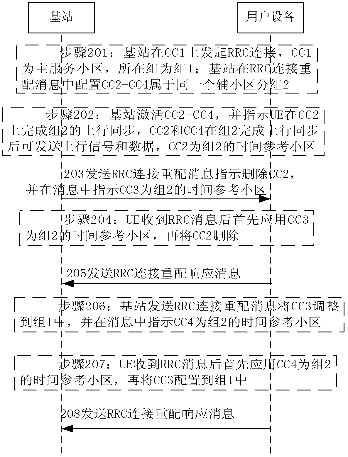
[0066] Such as figure 2 As shown, the method for modifying the time reference cell in this embodiment includes:

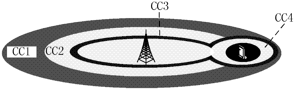
[0067] Step 201: UE initiates an RRC connection on CC1, and the base station configures CC2, CC3 and CC4 information and grouping information to UE in an RRC connection reconfiguration message;

[0068] CC1 is the primary serving cell, forming group 1, and CC2~CC4 are secondary serving cells, forming group 2;

[0069] Step 202: The base station activates CC2~CC4 when the UE is in the RRC connection state, and instructs CC2 to initiate a random access process to complete uplink synchronization; after group 2 completes uplink synchronization, it can send uplink signals on CC2~CC4, and CC2 acts as group 2 The time reference cell;

[0070] Step 203: After a period of time, when the base station needs to delete CC2, send an RRC connection reconfiguration message to indicate the deletion of CC2, and indicate in the message that CC3 is the time reference cell of group ...

Embodiment 2

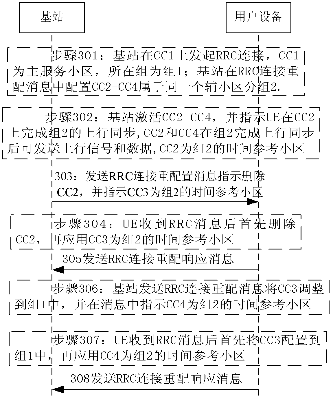
[0077] Such as image 3 As shown, the method for modifying the time reference cell in this embodiment includes:

[0078] Step 301: The UE initiates an RRC connection on CC1, and the base station configures CC2, CC3, and CC4 information and grouping information to the UE in an RRC connection reconfiguration message;

[0079] CC1 is the primary serving cell, forming group 1, and CC2-CC4 are secondary serving cells, forming group 2.

[0080] Step 302: The base station activates CC2~CC4 when the UE is in the RRC connection state, and instructs CC2 to initiate a random access process to complete uplink synchronization; group 2 can send uplink signals on CC2~CC4 after completing uplink synchronization, and CC2 serves as group 2 The time reference cell;

[0081] Step 303: After a period of time, the base station needs to delete CC2, send an RRC connection reconfiguration message to indicate the deletion of CC2, and indicate in the message that CC3 is the time reference cell of grou...

Embodiment 3

[0088] Such as Figure 4 As shown, the method for modifying the time reference cell in this embodiment includes:

[0089]Step 401: The UE initiates an RRC connection on CC1, and the base station configures CC2, CC3 and CC4 information and grouping information to the UE in an RRC connection reconfiguration message;

[0090] CC1 is the primary serving cell, forming group 1, and CC2-CC4 are secondary serving cells, forming group 2.

[0091] Step 402: The base station activates CC2~CC4 when the UE is in the RRC connection state, and instructs CC2 to initiate a random access process to complete uplink synchronization; after group 2 completes uplink synchronization, it can send uplink signals on CC2~CC4, and CC2 serves as group 2 The time reference cell;

[0092] Step 403: After a period of time, the base station needs to delete CC2, and the base station sends an RRC connection reconfiguration message to instruct to delete CC2;

[0093] Step 404: After receiving the RRC message, ...


PUM


Abstract

The invention discloses a modifying method and device for a time-reference cell. The modifying method for the time-reference cell comprises the following steps that when a user device is in a time reference cell which needs to change auxiliary service cell groups, a cell which needs to be used as the time reference cell is set to be the time reference cell of an auxiliary service cell at first, and then an original time reference cell is unusable in the auxiliary service cell group, or the user device enables the original time reference cell to be unusable in the auxiliary service cell, and then the cell which needs to be used as the time reference cell is set to be the time reference cell of the auxiliary service group, or the user device enables the original time reference cell to be unusable in the auxiliary service cell, and meanwhile the cell which needs to be used as the time reference cell is set to be the time reference cell of the auxiliary service cell group. The modifying method and device for the time-reference cell is capable of determining the selection time and the effect-taking time point of the time-reference cell of the auxiliary service cell group under a multi-TA-carrier wave gathering system.

Description

technical field [0001] The invention relates to the field of mobile communication, in particular to a method and device for modifying a time reference cell. Background technique [0002] Long Term Evolution Advance (LTE-Advanced for short) introduces many new technologies to meet the basic requirements of IMT-Advanced, and one of the most important technologies is carrier aggregation. [0003] Due to the current shortage of wireless spectrum resources, and IMT-Advanced requires higher peak rate indicators (100Mbps under high mobility and 1Gbps under low mobility), the maximum bandwidth of 20MHz in the current LTE standard cannot meet the requirements of IMT-Advanced. Advanced requires, so it needs to be expanded to a higher bandwidth, such as 40MHz, 60MHz, or even higher. One of the methods to increase the bandwidth and peak rate is to expand the frequency domain. For example, several 20MHz-based LTE frequency bands are expanded by "carrier aggregation", which is the essenc...

Claims


Application Information

Patent Timeline
IPC IPC(8): H04W76/04
Inventor 万璐陈中明
Owner ZTE CORP
Why Eureka
Try Eureka