Joystick capable of controlling direction rudder and accelerator synchronously

a technology of direction rudder and accelerator, which is applied in the field of joysticks, can solve the problems of injury to the user, difficult control of other function keys, and difficulty for the user to use joysticks

Inactive Publication Date: 2003-09-23
WEISTECH TECH CO LTD
View PDF5 Cites 49 Cited by
  • Summary
  • Abstract
  • Description
  • Claims
  • Application Information

AI Technical Summary

Problems solved by technology

However, such joysticks suffer from the following drawback:
Furthermore, the handle is not ergonomically designed and will often cause injury to the user.
Nonetheless, it is necessary for a user to use his left or right hand finger to control the direction control unit so that when the user controls the direction control unit, he will be very difficult to control other function keys.
3. In addition, the direction control unit and the acceleration control unit of the conventional joysticks are separately arranged in different positions thereby making it almost impossible to control the two units synchronously and also increasing the manufacturing cost.

Method used


Image

  • Joystick capable of controlling direction rudder and accelerator synchronously
  • Joystick capable of controlling direction rudder and accelerator synchronously
  • Joystick capable of controlling direction rudder and accelerator synchronously

Examples


Embodiment Construction

For the purpose of promoting an understanding of the principles of the invention, reference will now be made to the embodiment illustrated in the drawings. Specific language will be used to describe same. It will, nevertheless, be understood that no limitation of the scope of the invention is thereby intended, alterations and further modifications in the illustrated device, and further applications of the principles of the invention as illustrated herein being contemplated as would normally occur to one skilled in the art to which the invention relates.

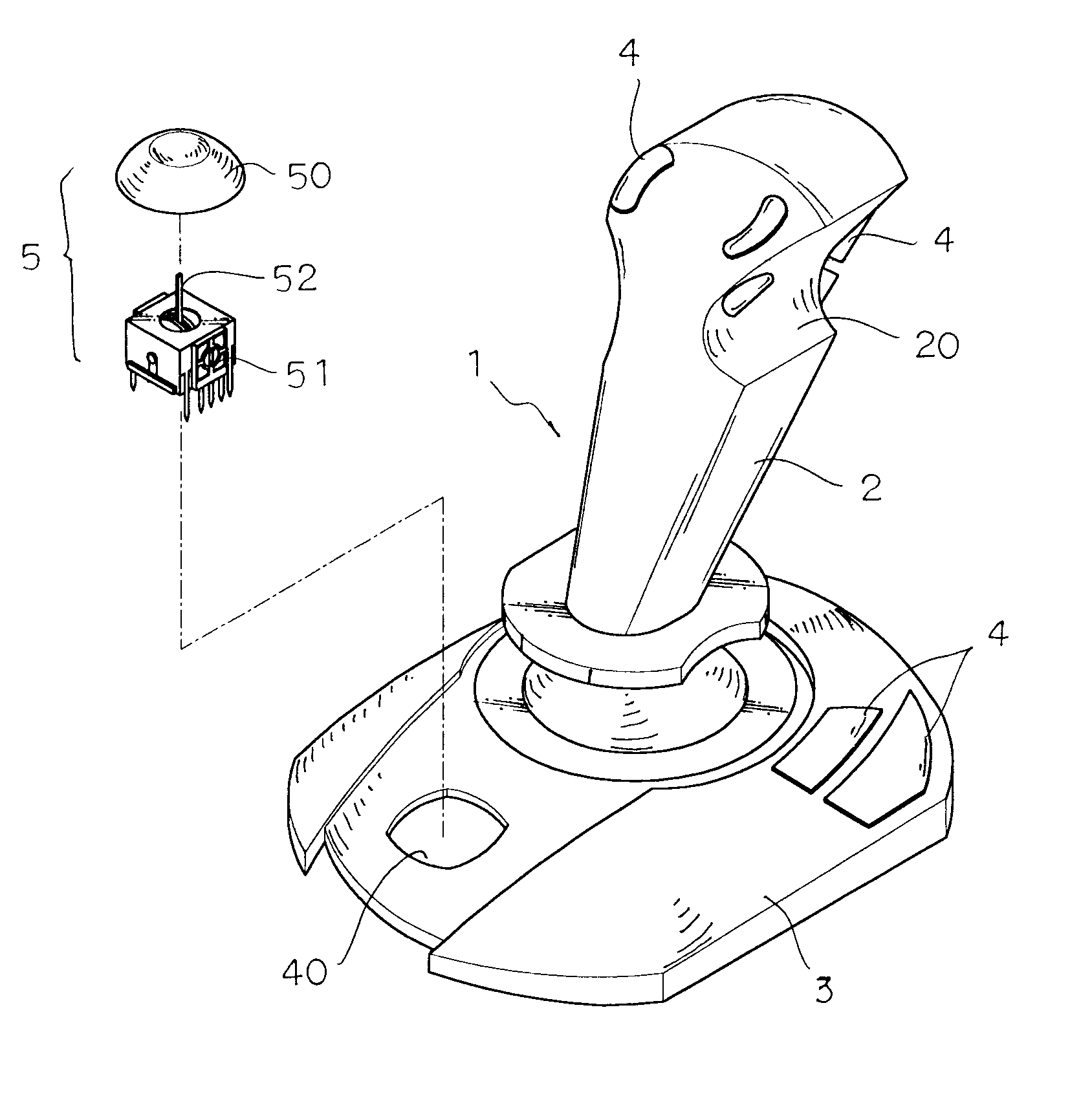
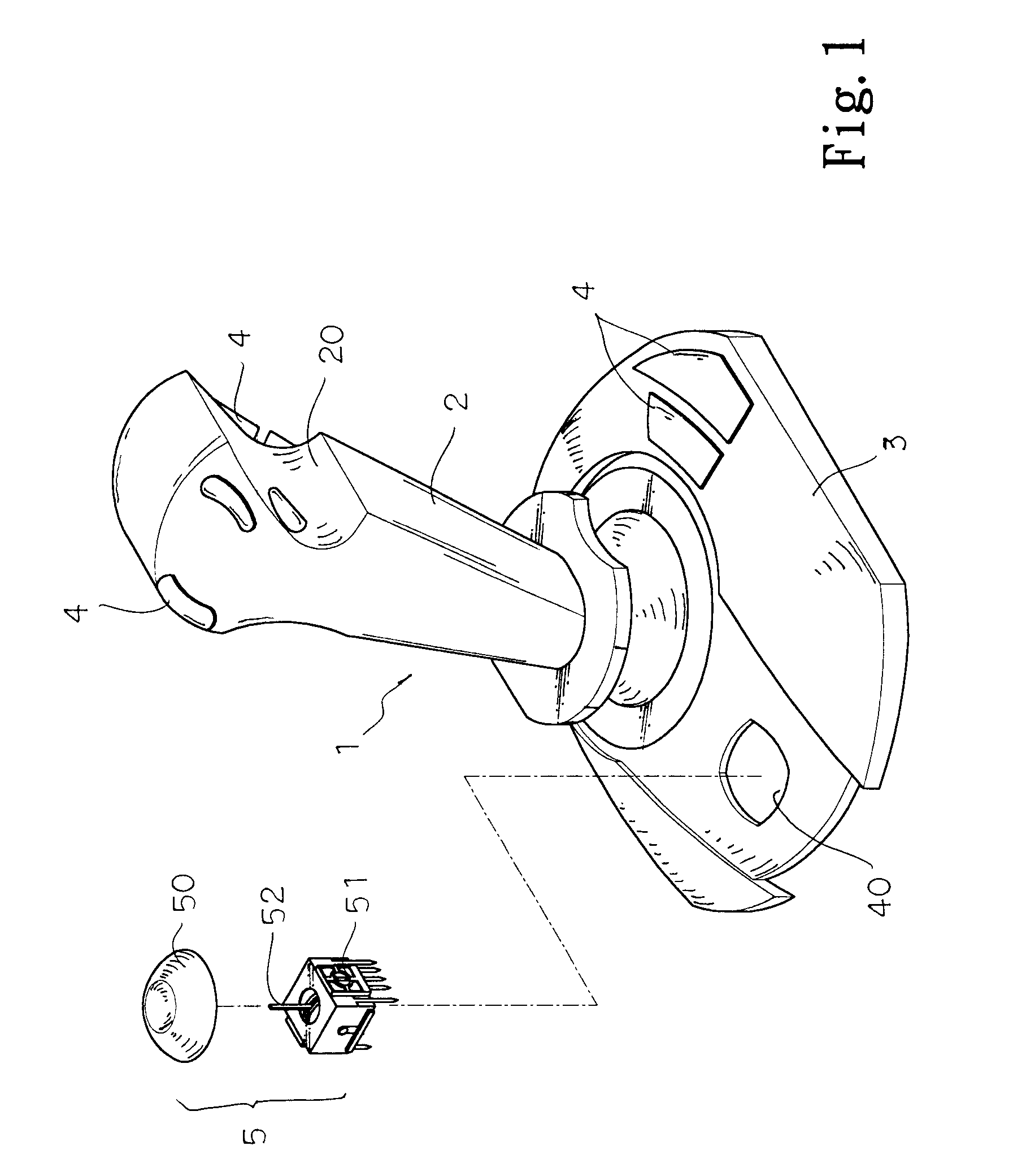
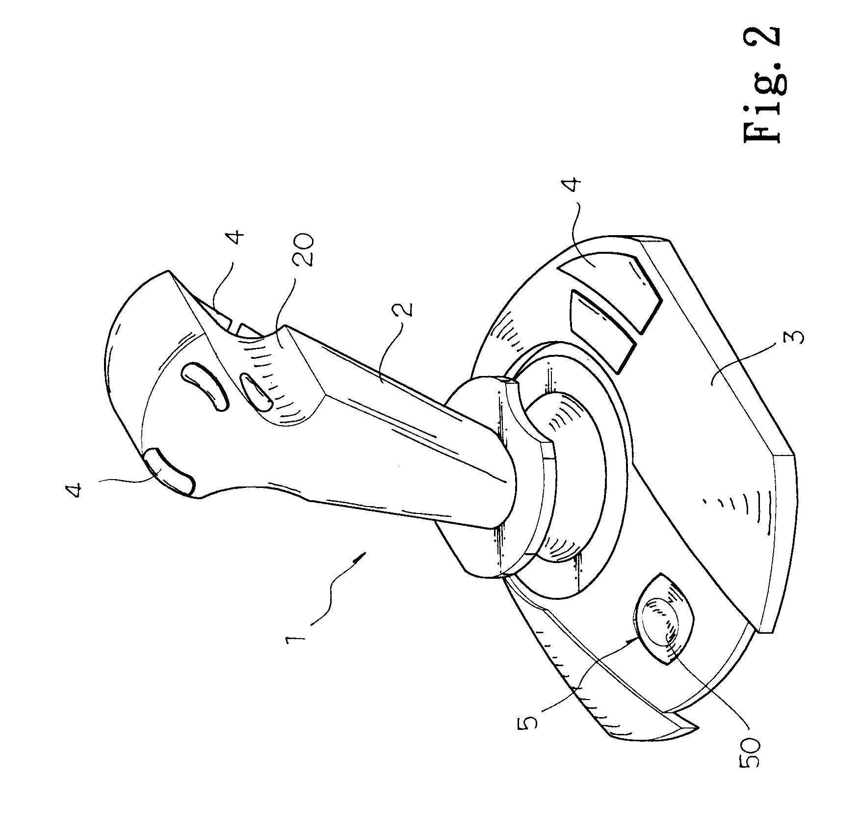
With reference to the drawings and in particular to FIGS. 1, 2 and 3 thereof, the present invention generally comprises a handle 2, a base 3 and a mini joystick 5.

The handle 2 has an ergonomic shape designed for ease of use, i.e. for maximum comfort and efficiency. The handle 2 is formed with two curved recesses 20 for receiving fingers. A plurality of functions keys 4 is provided at the upper end of the handle 2 for increasing variat...


PUM


Abstract

A joystick structure includes an ergonomic handle, a base on which is mounted the handle, and a mini joystick fitted in a cavity of the handle and including a button and a direction control unit, the direction control unit being provided with a control rod which is movable in two perpendicular directions, the control rod being able to return to an original position thereof when released for controlling direction, the control rod being able to stop at any position for controlling acceleration, whereby the direction control unit and acceleration control unit can be operated synchronously.

Description

1. Field of the InventionThis invention is related to an improvement in the structure of a joystick and in particular to one which can control the direction control unit and acceleration control unit synchronously.2. Description of the Prior ArtThe conventional joystick is a computing lever controlling a cursor, i.e. a hand-held control stick that allows a player to control the movements of a cursor on a computer screen or a symbol in a video game. The conventional joysticks 100 (see FIGS. 5, 6 and 7) generally include a base 300, a handle 200 mounted on the base 300 and a plurality of function keys 400 arranged on the base 300. However, such joysticks suffer from the following drawback:1. As shown in FIG. 6, the direction control unit is arranged within the handle and controlled by rotating the handle clockwise or counterclockwise. Nevertheless, as the handle 200 is also used for controlling the vector variation in X-axis and Y-axis and is controlled by the wrist, the handle 200 wi...

Claims


Application Information

Patent Timeline
Patent Type & Authority Patents(United States)
IPC IPC(8): G05G9/047G05G9/00
CPCG05G9/04788Y10T74/20201G05G2009/04774
Inventor HSU, WEI
Owner WEISTECH TECH CO LTD
Why Eureka
Try Eureka