Position feedback system and method for use thereof

a feedback system and position technology, applied in the field of moving elements, can solve the problems of inaccurate position data for moving elements, increased manufacturing cost, and reduced machine yield

Inactive Publication Date: 2003-09-23
TETRA LAVAL HLDG & FINANCE SA
View PDF44 Cites 861 Cited by
  • Summary
  • Abstract
  • Description
  • Claims
  • Application Information

AI Technical Summary

Problems solved by technology

One drawback to using encoders and resolvers for position feedback is that systems utilizing this type of feedback require homing to a known position before normal operation can begin.
Both these processes require movement of the movable elements, which is undesirable in a web-fed FFS machine, as this initialization process generally involves the rejection of packaging material and / or product.
This results in increased manufacturing cost and lower yield on the machine.
When the monitored component, for example the belt or gear, does not function properly, the position data for the movable element is not accurate.
In addition, a single, magnetostrictive sensor has a limited update speed making its use in high-speed applications problematic.

Method used


Image

  • Position feedback system and method for use thereof
  • Position feedback system and method for use thereof
  • Position feedback system and method for use thereof

Examples


Embodiment Construction

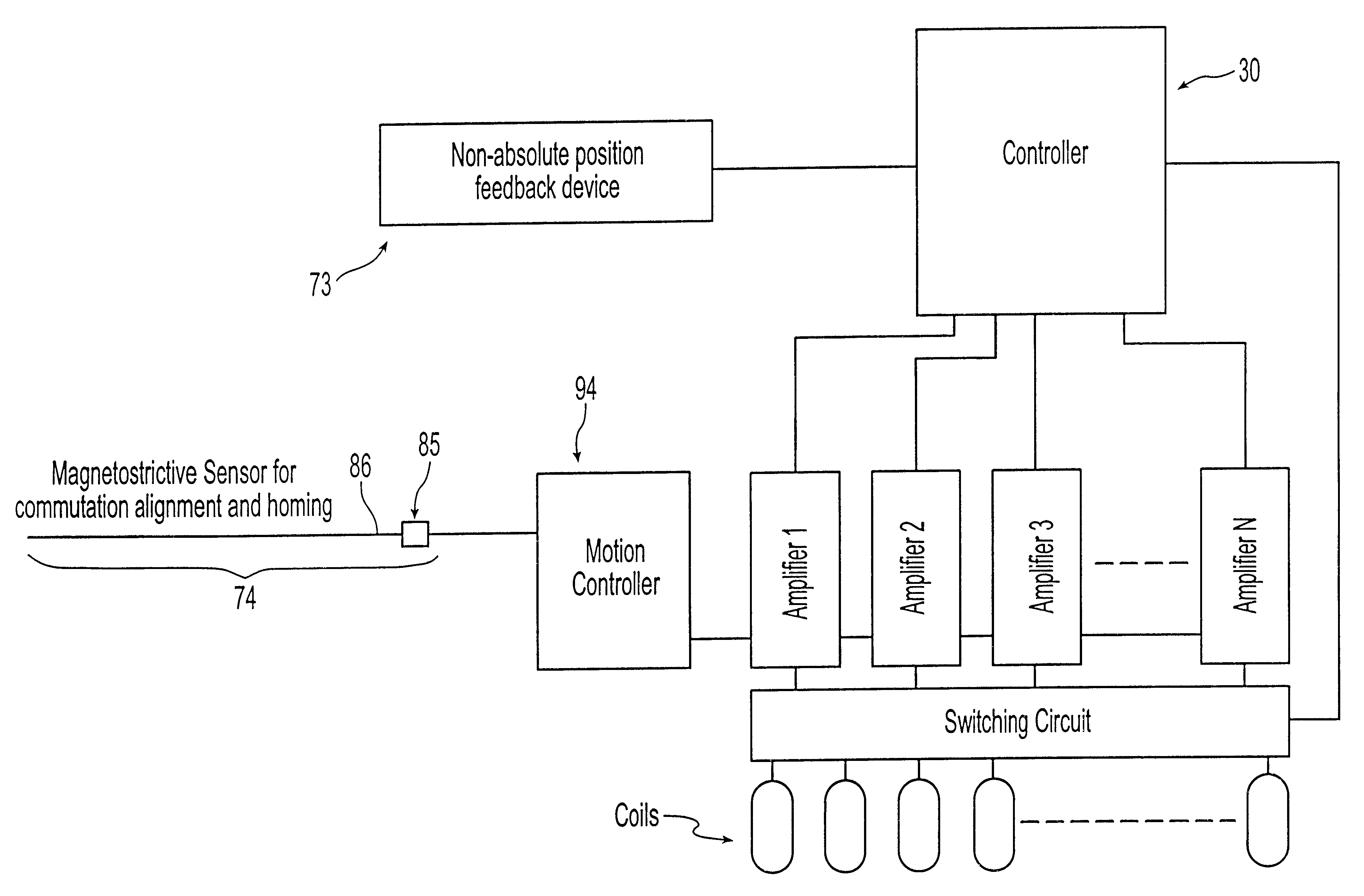
In the following description and appended claims the term "magnetostrictive sensor" is used to describe sensors with a head connected to a waveguide that are absolute position feedback sensors. In the following description and appended claims the term "non-absolute sensor" is used to describe step and direction type sensors or incremental sensors. In the following description and appended claims the term "programmable controller" or "controller" is used to describe an electronic component linked to the sensors. When more than one magnetostrictive sensor is used to programmable controller is the digital signal processor (DSP), discussed below, that links the sensors to the motion controller. Alternatively the microcontroller can replace the DSP. When only one magnetostrictive sensor is used to programmable controller is the motion controller that links the sensor to the drive. In this arrangement, if non-absolute sensors are used another programmable controller can be used to receive...


PUM

PropertyMeasurementUnit
magnetostrictiveaaaaaaaaaa
lengthsaaaaaaaaaa
movementaaaaaaaaaa

Abstract

The present invention is directed to a machine with a position feedback system and a method for use thereof. The machine includes at least one movable element mounted for movement on a path and at least one programmable controller. The machine further includes at least two absolute or magnetostrictive sensors or the machine includes an absolute sensor and a non-absolute sensor. The programmable controller uses positional information from the sensors to determine the position of the movable elements on the path and control the movable elements. The method includes determining a known position for the movable elements, linking at least two magnetostrictive sensors into one virtual sensor, and/or performing commutation alignment for the movable elements. Determining the position and commutation alignment can occur when the movable elements are stationary or moving.

Description

Technical FieldThe present invention relates to machines with moving elements, and more particularly to a system and method for determining the position of the moving elements and for using such position data in controlling such elements.Background of InventionPackaging machines that form a tube from a web of material are known. In these machines, a portion of the tube is filled with a product, such as fluid or other flowable product. Two, spaced portions on the tube are sealed transversely by a pair of sealing jaws in the packaging machine to form a closed package with the product therein. The tube is then severed through the sealed portions to separate the package from adjacent ones formed by the machine. This type of packaging machine is generally referred to as a form, fill and seal (FFS) machine.Commonly, each of the packages must be filled with a consistent volume of product. This consistency of volume can be provided by making the individual packages of equal volume when seal...

Claims


Application Information

Patent Timeline
Patent Type & Authority Patents(United States)
IPC IPC(8): B29C65/00B29C65/02B29C65/18B65B51/30B65B51/26B65B9/10B65B9/20G05B19/00
CPCB29C65/02B29C65/18B29C66/1122B29C66/1162B29C66/4312B29C66/4322B29C66/82263B29C66/8351B29C66/83523B29C66/83533B29C66/872B29C66/98B65B51/30G05B19/00B29C66/81419B29C66/81427B29C66/8181B29C66/3452B29C66/8226B29C66/8242B29C66/8244B29C66/83413B29C66/83415B29C66/849B29C66/8491B65B9/20B29C65/00B29C66/93441B29C66/93451B29C66/9392B29C65/3656B29C65/3668B29C65/368B29C66/8122B29C66/8161B29C66/49B29C66/8167B29C66/72321B29C66/72328B29C65/7451B29C66/73921B29K2705/02B29C66/133B29C65/7894B29K2909/02
Inventor BOGDANOV, EMIL D.ORTIZ, MARK S.ARMS, DONALD A.BOLOGNA, GREGORY A.RESTLE, RANDALL C.
Owner TETRA LAVAL HLDG & FINANCE SA
Why Eureka
Try Eureka