Adjustable dental impression tray and methods for using same

a dental impression and adjustment technology, applied in the field of dental implements, can solve the problems of providing means for structural adjustment, difficulty in maintaining proper cleaning and sanitation of the impression trays, and prior art dental impression trays made of metal

Inactive Publication Date: 2003-10-07
SKINNER GREGORY C
View PDF25 Cites 38 Cited by
  • Summary
  • Abstract
  • Description
  • Claims
  • Application Information

AI Technical Summary

Benefits of technology

In view of the foregoing, it is a primary object of the present invention to provide novel dental impression trays which may be mechanically adjusted to accommodate various mouth sizes, bite radii of teeth, and to correspond to upper, lower, anterior, quadrant, or triple bite impression sites.
The outer wall of at least one of the arcuate members may include a notch adjacent the proximal end of the arcuate member which permits the user to break arcuate member at the notch. This notch allows the user to create a "quadrant" dental tray for taking an impression of the upper or lower left or right portions of the patient's dentition, by breaking off the appropriate arcuate member at the notch. The outer wall of the arcuate members may also include a notch positioned adjacent a middle portion of each arcuate member between the distal and proximal ends. This notch allows the user to break the arcuate members to create an "anterior" dental tray for taking a dental impression of the front portion of the patient's upper or lower dentition.

Problems solved by technology

Although seemingly useful for their intended purposes, there are several practical disadvantages of prior art dental impression trays comprised of metal.
For example, a significant disadvantage of prior art metal impression trays includes the difficulty associated with maintaining proper cleaning and sanitation of the impression trays using heat or chemical sterilization methods or techniques to avoid cross-contamination in order to be able to reuse the various sized stock metal impression trays from patient to patient.
A meaningful disadvantage with prior art adjustable impression trays of the general type disclosed herein is that they only provide means for accommodating a structural adjustment in the dimensional length of the channel.
In this regard, because these prior art adjustable impression trays fail to provide for any adjustment in the dimensional width associated with various sizes of the dental arch, they are generally limited in their particular utilization.
While prior art adjustable and heat-expansive impression trays may appear generally suitable for their intended purposes, these prior art impression trays nevertheless leave much to be desired from the standpoint of effectiveness of operation, manufacturing costs, simplicity of construction in relation to a multiplicity of parts, and functionality as to universal application.
As will be appreciated in this particular art, economic considerations are significant when dealing with the highly competitive dental industry, since multiple stock impression trays (e.g., small, medium, and large) or complicated devices are frequently found to be commercially impractical.

Method used


Image

  • Adjustable dental impression tray and methods for using same
  • Adjustable dental impression tray and methods for using same
  • Adjustable dental impression tray and methods for using same

Examples


Embodiment Construction

It will be readily understood that the components of the present invention, as generally described and illustrated in the Figures herein, could be arranged and designed in a wide variety of different configurations. Thus, the following more detailed description of the embodiments of the system and method of the present invention, as represented in FIGS. 1 through 7, is not intended to limit the scope of the invention, as claimed, but it is merely representative of the presently preferred embodiments of the invention. The presently preferred embodiments of the invention will be best understood by reference to the drawings, wherein like parts are designated by like numerals throughout.

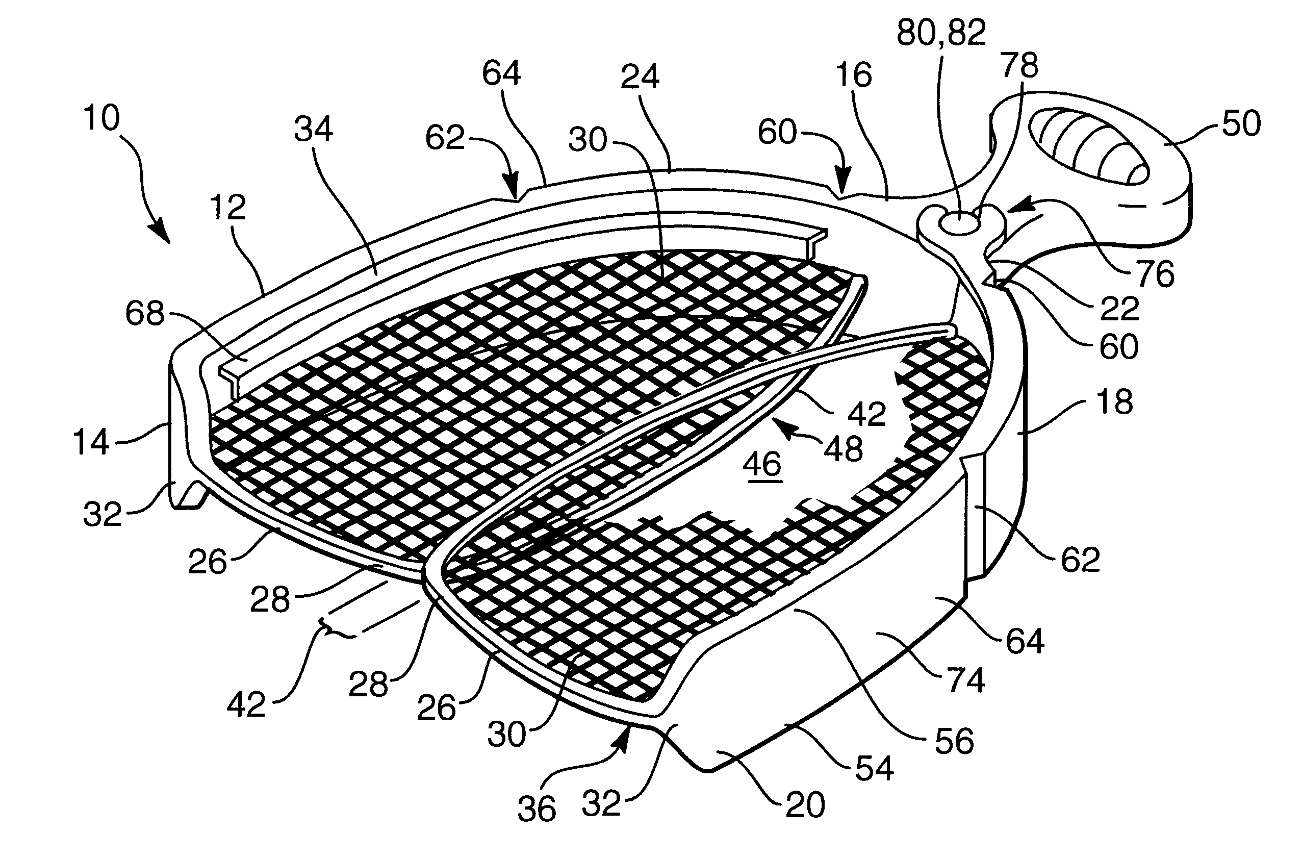
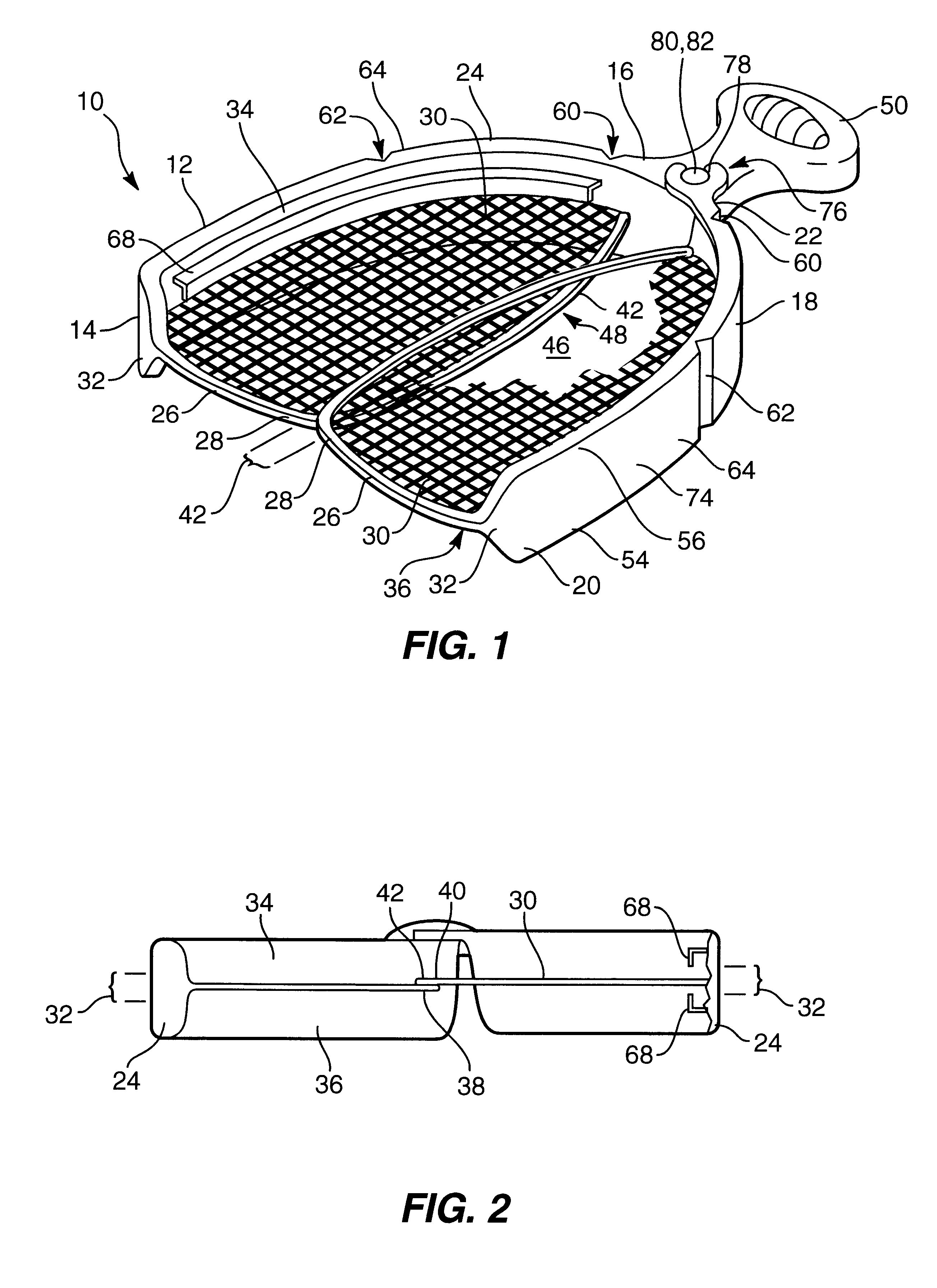
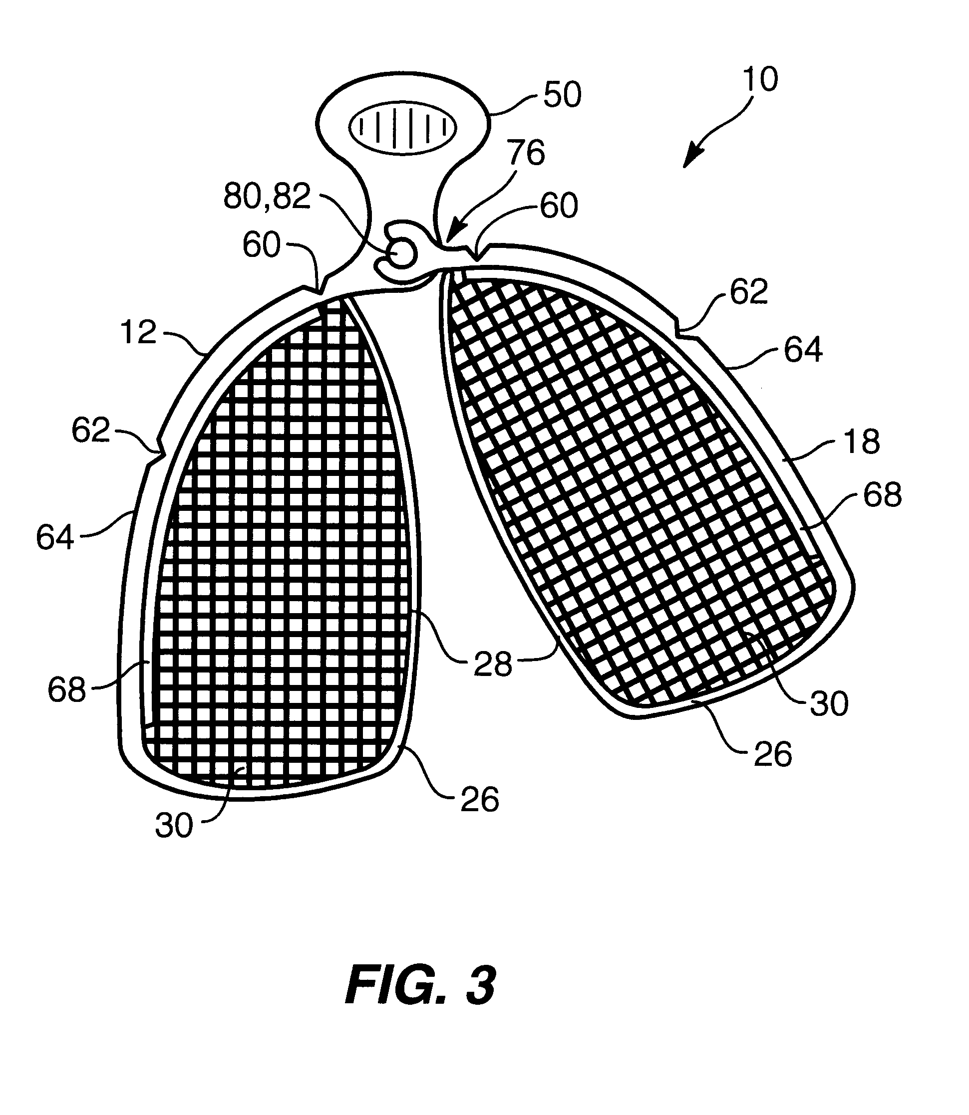
One presently preferred embodiment of the present invention, designated generally at 10, is best illustrated in FIG. 1. As shown, an adjustable dental impression tray 10 includes a first arcuate member 12 having a distal end 14 and a proximal end 16. A second arcuate member 18 having a distal end 20 and ...


PUM


Abstract

An adjustable dental impression tray includes a first and second arcuate member movably attached at a proximal end of each arcuate member. The adjustable dental impression tray includes a handle to facilitate removal of the tray from a person's mouth. The dental impression tray also includes an adjustment mechanism which allows the user to position the first arcuate member relative to the second arcuate member to form a U-shaped channel which approximates the patients dentition. The dental impression is further configured with a locking member to receive and retain impression material into the tray.

Description

1. Field of the InventionThis invention relates to dental implements, and more particularly, to novel dental impression trays that are mechanically adjustable to accommodate various mouth sizes in order to obtain an accurate impression of the upper and / or lower dentition of a patient.2. The Background ArtWith regards to dentistry, an impression is often used to create an imprint or negative likeness of the teeth and adjacent portions of the jaw (e.g., tooth formations, the contour of the gums, etc.) preparatory to dental repair, orthodontics and restoration of missing dental structures. Impressions are typically made by placing a soft, semi-fluid material within the confines of an open trough or channel of an arcuate tray which is then positioned within the mouth of a patient, thus allowing the material to set or cure. Depending upon the material used, the set impression may be either hard or have some elastic characteristics.To provide the most accurate articulation, the impression...

Claims


Application Information

Patent Timeline
Patent Type & Authority Patents(United States)
IPC IPC(8): A61C9/00
CPCA61C9/0006
Inventor SKINNER, GREGORY C.
Owner SKINNER GREGORY C
Why Eureka
Try Eureka