Brake cable connecting apparatus for drum brake

a technology of connecting apparatus and brake cable, which is applied in the direction of mechanical equipment, brake systems, transportation and packaging, etc., can solve the problems of reducing the work efficiency of connecting brake cable, increasing the chance of misassembling brake cable, and increasing the cost, so as to achieve the same level of effectiveness, without large cable operation force, and prevent sacrifice of work efficiency

Inactive Publication Date: 2003-11-04
AH BRAKE CO LTD
View PDF6 Cites 2 Cited by
  • Summary
  • Abstract
  • Description
  • Claims
  • Application Information

AI Technical Summary

Benefits of technology

An object of a first invention is to provide a brake cable connecting apparatus which realizes a way to prevent the inadvertent disengagement of a cable end of a brake cable from a brake lever of a brake-actuating mechanism based on a different concept as used in the conventional ways or methods. This invention, which fundamentally using existing members without an additional member, accurately prevents the inadvertent disengagement of the cable end from notched grooves of a free end of the brake lever. Further, this invention eliminates necessary large cable operation force at the time of snapping the cable end in the notched groove. Accordingly, there is no need to sacrifice the work efficiency for connecting the brake cable and create a chance of damaging or deforming the cable end and / or the mouths of the notched grooves, thereby surely preventing the inadvertent disengagement of the cable end from the notched grooves.
The third invention achieves the same level of effectiveness as in the first invention by way of providing the returning force of the brake lever by using a lever return spring.

Problems solved by technology

In such a case, the brake cable 5 can easily be disconnected from the brake-actuating mechanism 6, causing a notable decrease in work efficiency for connecting the brake cable and increasing a chance of misassembling of the brake cable.
However, between the above-described conventional ways of preventing the inadvertent disengagement of the cable end from the brake lever, the former way described in FIG. 15 requires the high-costly V-shaped plate spring 8 as an additional member which relatively increases the cost of the brake-actuating mechanism 6 while the latter way described in FIGS. 16(a) and 16(b) requires a larger cable operating force in a process of snapping the cable end in the notched grooves 4a, which not only decreases work efficiency for snapping the cable end in but also creates a chance of damaging and deforming the cable end 5a and / or the mouths of the notched grooves 4a during the process.

Method used


Image

  • Brake cable connecting apparatus for drum brake
  • Brake cable connecting apparatus for drum brake
  • Brake cable connecting apparatus for drum brake

Examples


Embodiment Construction

Embodiments of present invention will now be described in detail with reference to the drawings.

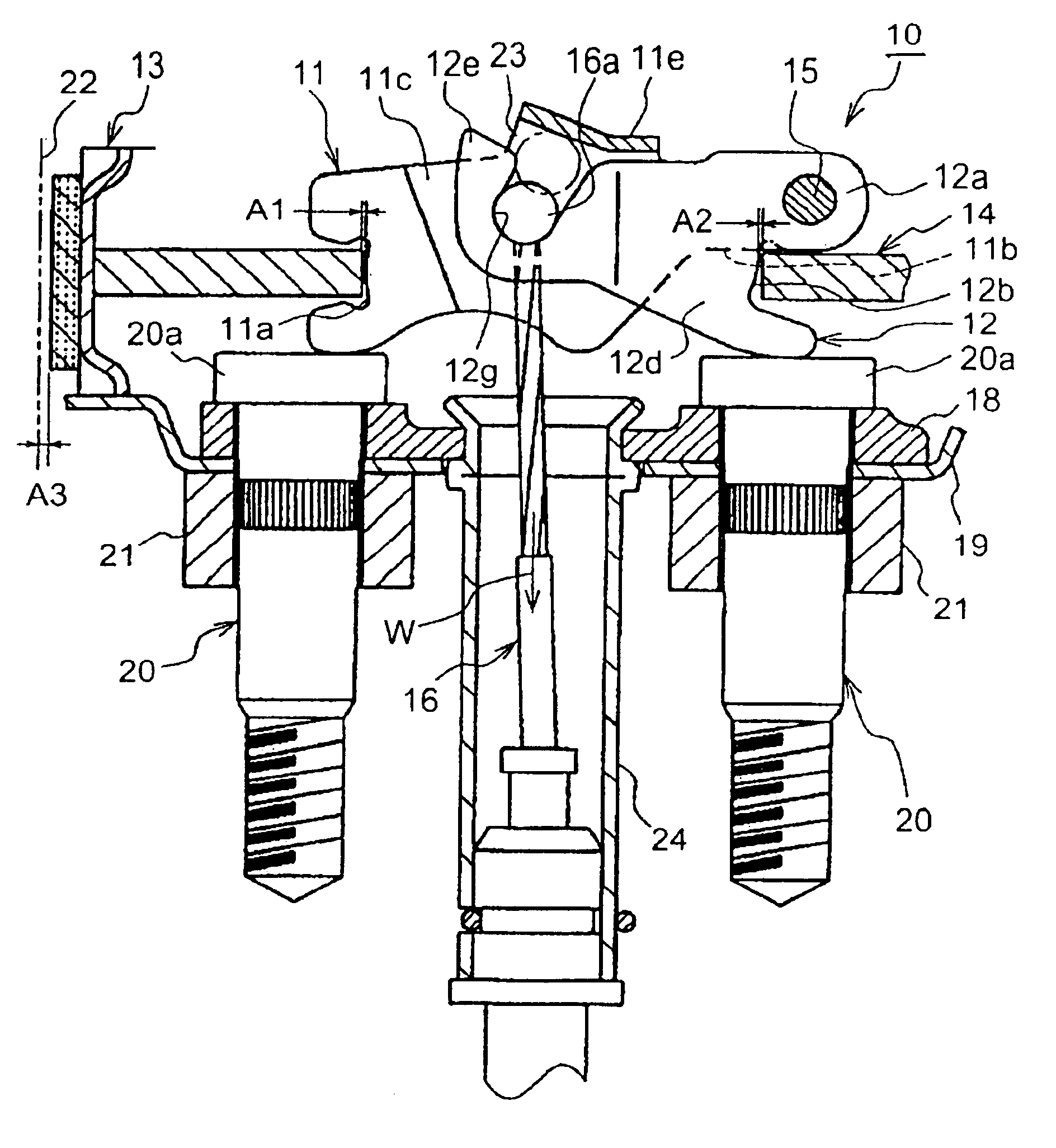
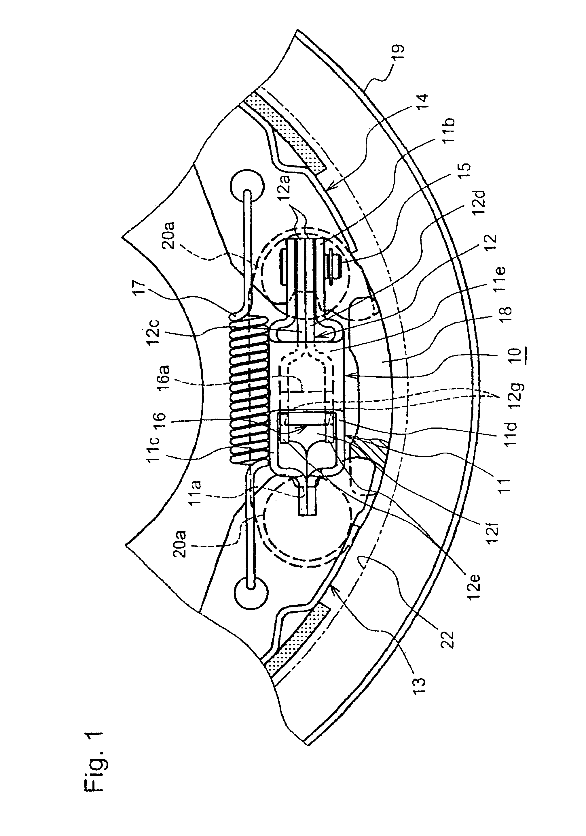
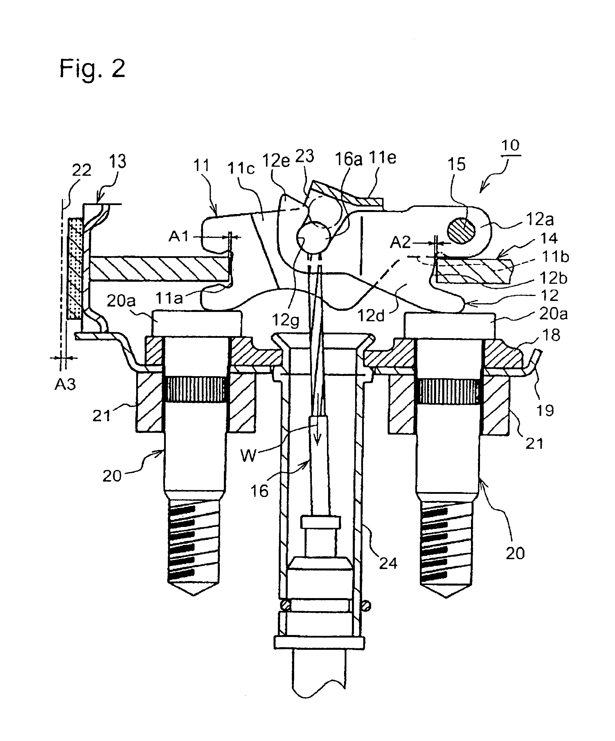
A brake-actuating mechanism 10 with a brake cable connecting apparatus according to one example is illustrated in FIGS. 1 and 2. FIGS. 3-8 respectively show a process of connecting a brake cable 16 to the brake-actuating mechanism 10.

Components of the brake-actuating mechanism 10 are explained with FIGS. 1 and 2 which mainly includes a strut 11 and a brake lever 12.

The strut 11 is disposed between respective operating ends of brake shoes 13, 14. A brake shoe engagement groove 11a is formed at one end of the strut 11 so as to be engaged with one brake shoe 13.

A base end 12a of the brake lever 12 is pivotally attached to the other end 11b of the strut 11 by means of a pivot pin 15. A brake shoe engagement groove 12b of the brake lever 12 is formed adjacent to such a pivotal attachment portion so as to be engaged with the other brake shoe 14.

The strut 11 is formed as a rectangular frame body...


PUM


Abstract

A brake cable connecting apparatus is structured to prevent the inadvertent disengagement of a cable end from the brake lever while transporting a drum brake. The bridge portion (11e) of the strut (11) extends above the free end (12e) of the brake lever (12) leaving a clearance (23), being smaller than the cable end (16a), therebetween. When the brake lever (12) rotates to the predetermined degree, the clearance (23) becomes larger than the cable end (16a) so that the cable end (16a) is able to pass through the clearance (23) between the bridge portion (11e) and the free end (12e).

Description

BACKGROUND OF THE INVENTION1. Field of the InventionThis invention relates to a brake-actuating mechanism for use on a drum brake device, designed to mechanically move a pair of brake shoes away from each other in response to operation of a brake lever. More particularly, it relates to a brake cable connecting apparatus designed to prevent the inadvertent disconnection of a brake cable from the brake lever, even during the transportation of the drum brake device with the brake cable already connected to the brake lever of the brake-actuating mechanism.2. Description of Related ArtPreviously, one known type of a prior art brake cable connecting apparatus in a brake-actuating mechanism as described above is illustrated in FIG. 15, disclosed in the U.S. Pat. No. 5,311,793.In FIG. 15, a pair of brake shoes is identified by reference numerals 1 and 2, respectively. A strut, a brake lever and a brake cable are identified by reference numerals 3, 4 and 5, respectively. The strut 3 and the ...

Claims


Application Information

Patent Timeline
Patent Type & Authority Patents(United States)
IPC IPC(8): B60T11/04B60T11/00F16D65/14F16D65/22F16D65/16F16C1/12F16D65/28
CPCB60T11/046F16C1/12F16D51/48F16D65/22Y10T74/20462F16D2125/60F16D2125/62F16D2125/68F16D2250/0084F16D2121/14F16C2361/45
Inventor IKEDA, TAKASHI
Owner AH BRAKE CO LTD
Why Eureka
Try Eureka