Connector

a technology of connecting rods and connectors, applied in the direction of securing/insulating coupling contact members, coupling device connections, incorrect coupling prevention, etc., can solve the problems of large housing, accidental inserting of the connector to the main stopping position,

Inactive Publication Date: 2003-12-02
SUMITOMO WIRING SYST LTD
View PDF12 Cites 12 Cited by
  • Summary
  • Abstract
  • Description
  • Claims
  • Application Information

AI Technical Summary

Problems solved by technology

However, in the above configuration. since the retainer protrudes when in the temporary stopping position, there is the danger that the retainer may be accidentally inserte...

Method used


Image

  • Connector
  • Connector
  • Connector

Examples


Embodiment Construction

An embodiment of the present invention is described below with the aid of FIGS. 1 to 18.

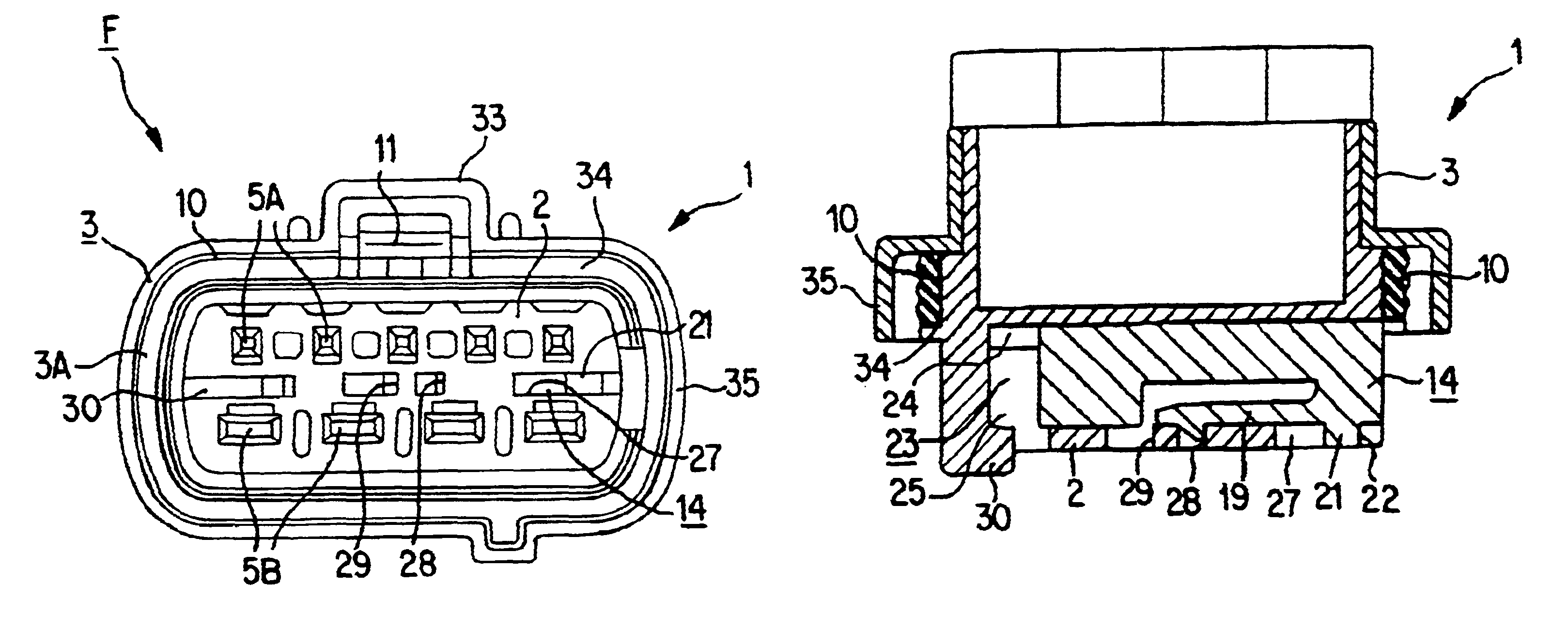
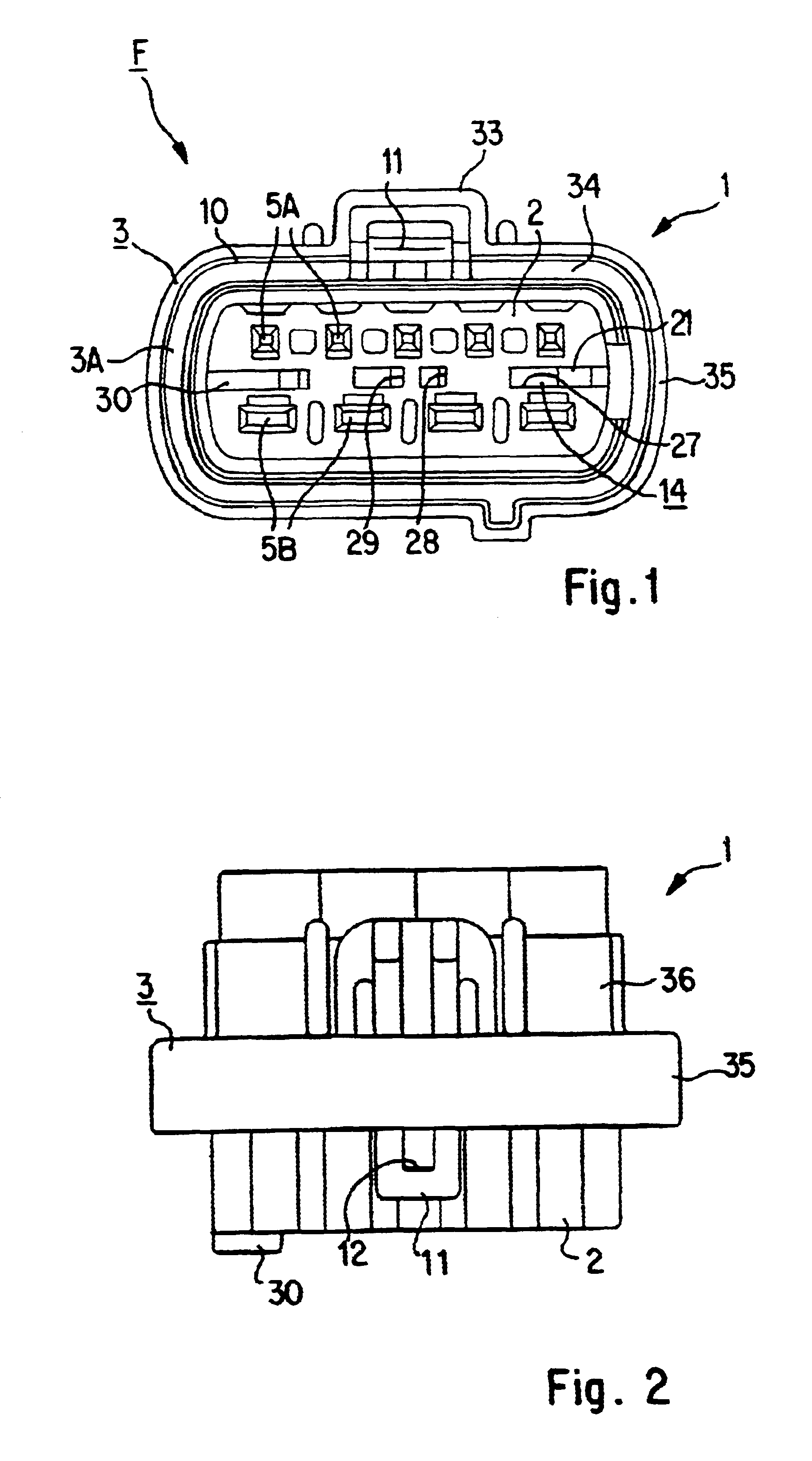
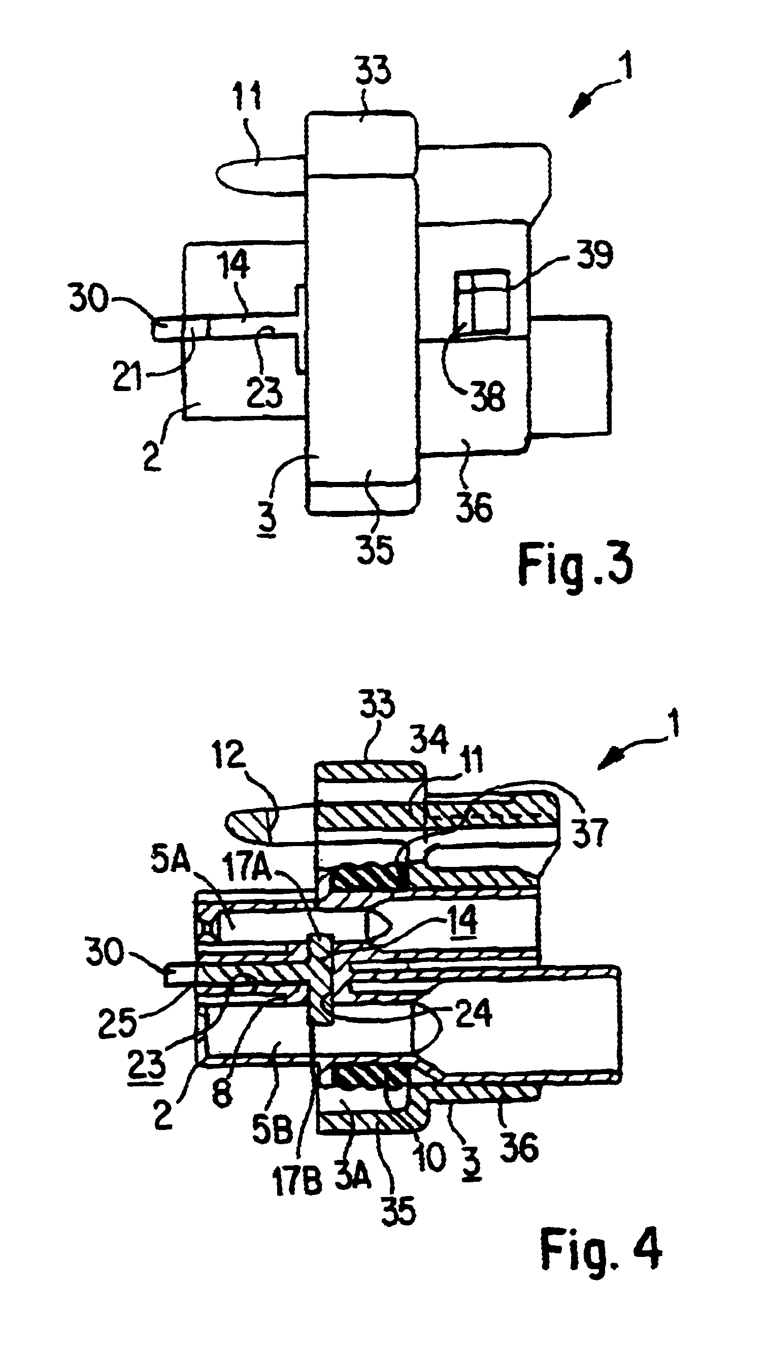
The present embodiment is provided with a pair of hybrid male and female waterproof connectors capable of fitting mutually together. First the female connector F will be explained with the aid of FIGS. 1 to 11.

The female connector F has a female housing 1 formed from plastic and, as shown in FIGS. 1 to 4, this comprises a housing main body 2 which has a cross-sectionally oblong shape and a hood 3 which is formed separately and attached thereto to define an annular chamber 3A.

Five small cavities 5A are formed in an aligned manner at an upper level within the housing main body 2, and four large cavities 5B are formed in an aligned manner at a lower level within the housing main body 2. Small female terminal fittings 6A are inserted into the small cavities 5A, and large female terminal fittings 6B are inserted into the large cavities 5B, these terminal fittings 6A and 6B being inserted from the post...


PUM


Abstract

A connector is capable of being miniaturised, whilst inadvertent pushing in of a retainer is prevented. A housing main body 2 into which female terminal fittings are inserted has a retainer insertion groove 23 formed on a side face thereof, a retainer 14 being inserted into this retainer insertion groove 23. The retainer 14 is maintained in a temporary stopping position which allows the insertion of the female terminal fittings into cavities thereof. After that, the retainer 14 is pushed further in and maintained in a main stopping position where is engages stepped members of the female terminal fittings. When the retainer 14 is in the temporary stopping position, the posterior end (relative to the direction of insertion) of this retainer 14 is inside the housing main body 2. As a result, the retainer 14 is not pushed inadvertently into the main stopping position while, for example, the connector is being transported to a site where the female terminal fittings are to be inserted. A hood member 35 does not need to perform the function of protecting the retainer 14, consequently its size can remain small so as merely to cover a sealing ring 10.

Description

The present invention relates to an electrical connector provided with a side retainer.BACKGROUND TO THE INVENTIONOne type of connector is provided with a side retainer. In this type of connector, a retainer insertion opening is formed on a side face of a housing provided with a plurality of cavities, and a retainer is inserted into this retainer insertion opening. This retainer is provided with a stopping protrusion capable of being engaged against stepped members or the like formed on the terminal fittings. Once the retainer has been inserted, first the stopping protrusions move away to sides of the cavities and the retainer is maintained in a temporary stopping position and, in that state, the terminal fittings can be inserted into the cavities and are engaged by lances. Next the retainer is pushed in further to a main stopping position, the stopping protrusions protrude into the cavities and are engaged against the stepped members of the terminal fittings, thereby doubly stoppin...

Claims


Application Information

Patent Timeline
IPC IPC(8): H01R13/436H01R13/641H01R13/64H01R13/52H01R13/42
CPCH01R13/4362H01R13/641H01R13/5219
Inventor KURIMOTO, NAOYA
Owner SUMITOMO WIRING SYST LTD
Why Eureka
Try Eureka