Cyclic slurry feeding system of coating machine

A coating machine and slurry technology, applied in the field of coating machine slurry circulation feeding system, can solve problems such as no good solution, achieve good coating quality consistency, reduce coating particles, and improve utilization rate Effect

Inactive Publication Date: 2013-02-20
JIANGSU FREY NEW ENERGY
View PDF6 Cites 13 Cited by
  • Summary
  • Abstract
  • Description
  • Claims
  • Application Information

AI Technical Summary

Problems solved by technology

There is no good

Method used


Image

  • Cyclic slurry feeding system of coating machine

Examples


Embodiment 1

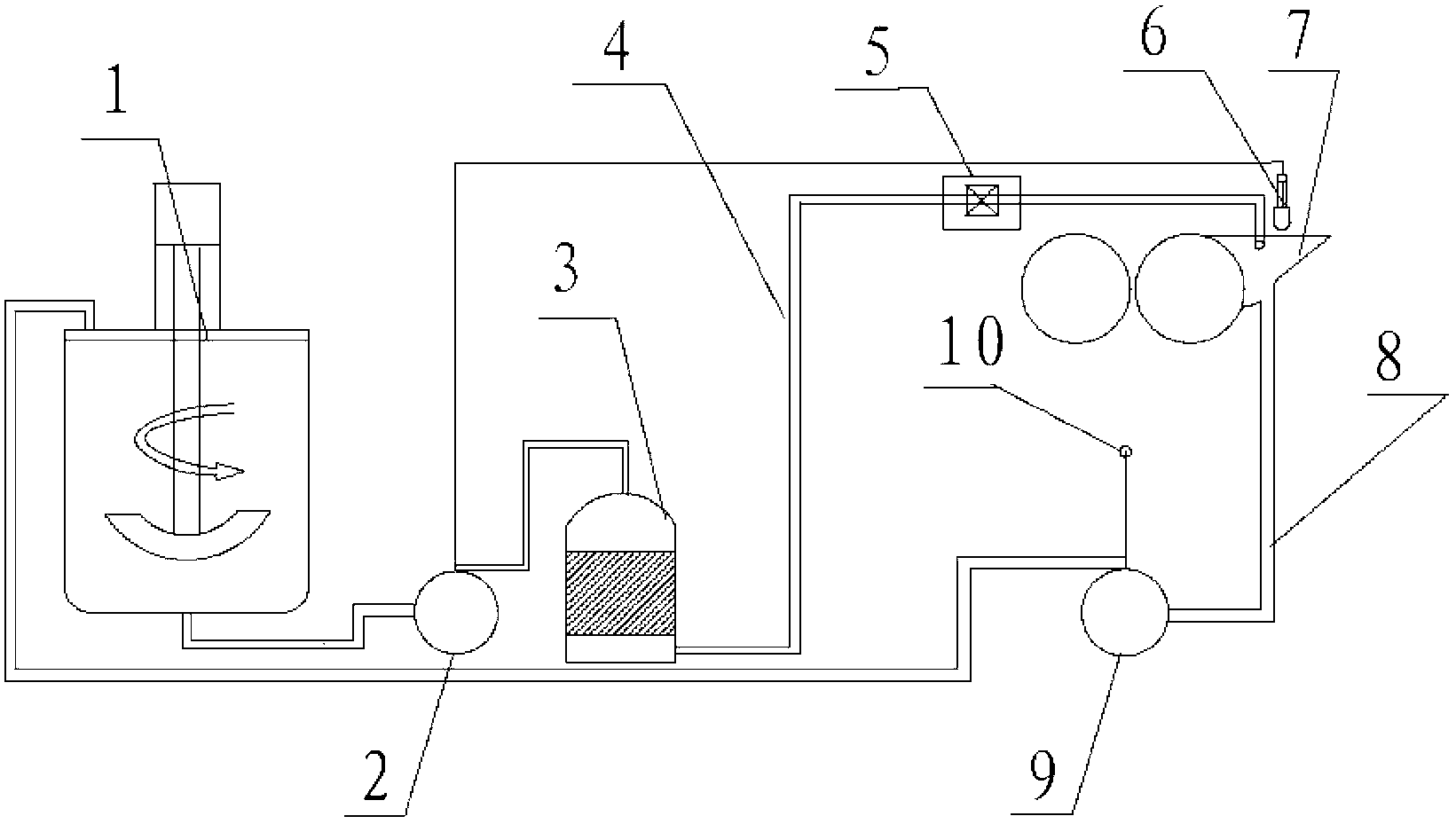
[0014] As shown in the figure: a coating machine slurry circulation feeding system, the system includes a slurry transfer tank 1, the top and bottom of the slurry transfer tank are respectively connected with a return pipeline 8 and a feeding pipeline 4; The circulating feeding system includes an automatic feeding part and an automatic returning part; wherein the feeding part includes a feeding diaphragm pump 2, a slurry filtering iron remover 3 and a liquid level sensor 6; the feeding diaphragm pump and the slurry filtering remove The ironware is connected to the coater trough 7 through the feeding pipeline; the return part includes the return diaphragm pump 9 and the controller 10 on it, and the slurry transfer tank 1 and the coater trough are respectively connected through the return pipeline 7.

[0015] The feeding diaphragm pump 2 is controlled by a liquid level sensor 6 located in the feed tank 7 of the coater.

[0016] The slurry transfer tank 1 is made of stainless st...

Embodiment 2

[0020] As shown in the figure: a coating machine slurry circulation feeding system, the system includes a slurry transfer tank 1, the top and bottom of the slurry transfer tank are respectively connected with a return pipeline 8 and a feeding pipeline 4; The circulating feeding system includes an automatic feeding part and an automatic returning part; wherein the feeding part includes a feeding diaphragm pump 2, a slurry filtering iron remover 3 and a liquid level sensor 6; the feeding diaphragm pump and the slurry filtering remove The ironware is connected to the coater trough 7 through the feeding pipeline; the return part includes the return diaphragm pump 9 and the controller 10 on it, and the slurry transfer tank 1 and the coater trough are respectively connected through the return pipeline 7.

[0021] The feeding diaphragm pump 2 is controlled by a liquid level sensor 6 located in the feed tank 7 of the coater.

[0022] The slurry transfer tank 1 is made of stainless st...


PUM


Abstract

The invention relates to coating processing equipment, in particular relates to a cyclic slurry feeding system of a coating machine, and belongs to the technical field of mechanical-electrical integration. The system comprises an automatic feeding part and an automatic material-returning part, wherein the conveying speed of slurry is controlled according to a flow difference between a feeding diaphragm pump and a material-returning diaphragm pump; and the designed flow of the material-returning diaphragm pump is relatively low and is generally less than 1 m<3>/h, and the designed flow of the feeding diaphragm pump is 2 to 3 times of that of the material-returning diaphragm pump. The feeding diaphragm pump automatically runs according to a liquid level signal; the flow of the feeding diaphragm pump is higher than that of the material-returning diaphragm pump, the liquid level of a material tank can be controlled in a cyclic slurry conveying process; and moreover, the slurry feeding conveying speed can be stabilized. With the adoption of the cyclic slurry feeding system of the coating machine, under temporary stopping, such as technical stopping and fault stopping in a coating process, slurry in the material tank can be conveyed into a slurry transferring tank through the automatic material-returning part, so that the utilization rate of the slurry is increased.

Description

technical field [0001] The invention relates to coating processing equipment, in particular to a coating machine slurry circulation feeding system, which belongs to the technical field of electromechanical integration. Background technique [0002] The application of coating processing technology and equipment in the field of lithium-ion battery production has a history of more than 20 years. With the development of lithium-ion battery technology and products, lithium-ion battery coating technology and equipment are also developing. At present, lithium-ion battery coating technology is divided into two types, namely transfer coating and extrusion coating. Transfer coating is the main coating form in lithium-ion batteries due to its small investment, small footprint and convenient use and maintenance. The main feature of transfer coating is that there is a trough on the front side of the coating roller, and a certain amount of slurry is temporarily stored in the trough, and ...

Claims


Application Information

Patent Timeline
IPC IPC(8): B05C11/10
Inventor 施华军胡正海曾福张引
Owner JIANGSU FREY NEW ENERGY
Why Eureka
Try Eureka