Connector

a technology of connecting rods and connecting rods, applied in the direction of incorrect coupling prevention, coupling device connection, electrical equipment, etc., can solve the problems of detecting members not being able to maintain in the waiting position or the operating position, and the resilience of the resilient stopping arm may los

Inactive Publication Date: 2002-09-03
SUMITOMO WIRING SYST LTD
View PDF3 Cites 14 Cited by
  • Summary
  • Abstract
  • Description
  • Claims
  • Application Information

AI Technical Summary

Benefits of technology

Such an arrangement ensures that the resilient legs of the detecting member do not lose resilience during the period of connection of the housings.
Preferably the recesses of the hood comprises channels open to the rear side, thus permitting moulding of the first housing without the use of removable inserts.

Problems solved by technology

If the resilient stopping arm remains in this state for a long period, the creep phenomenon may affect the resilience thereof, and the resilient stopping arm may lose its resilience.
Consequently, after the connector has temporarily been separated for maintenance or the like, it is possible that the detecting member cannot be maintained in the waiting position or the operating position when the two housings are again fitted together.

Method used


Image

  • Connector
  • Connector
  • Connector

Examples


Embodiment Construction

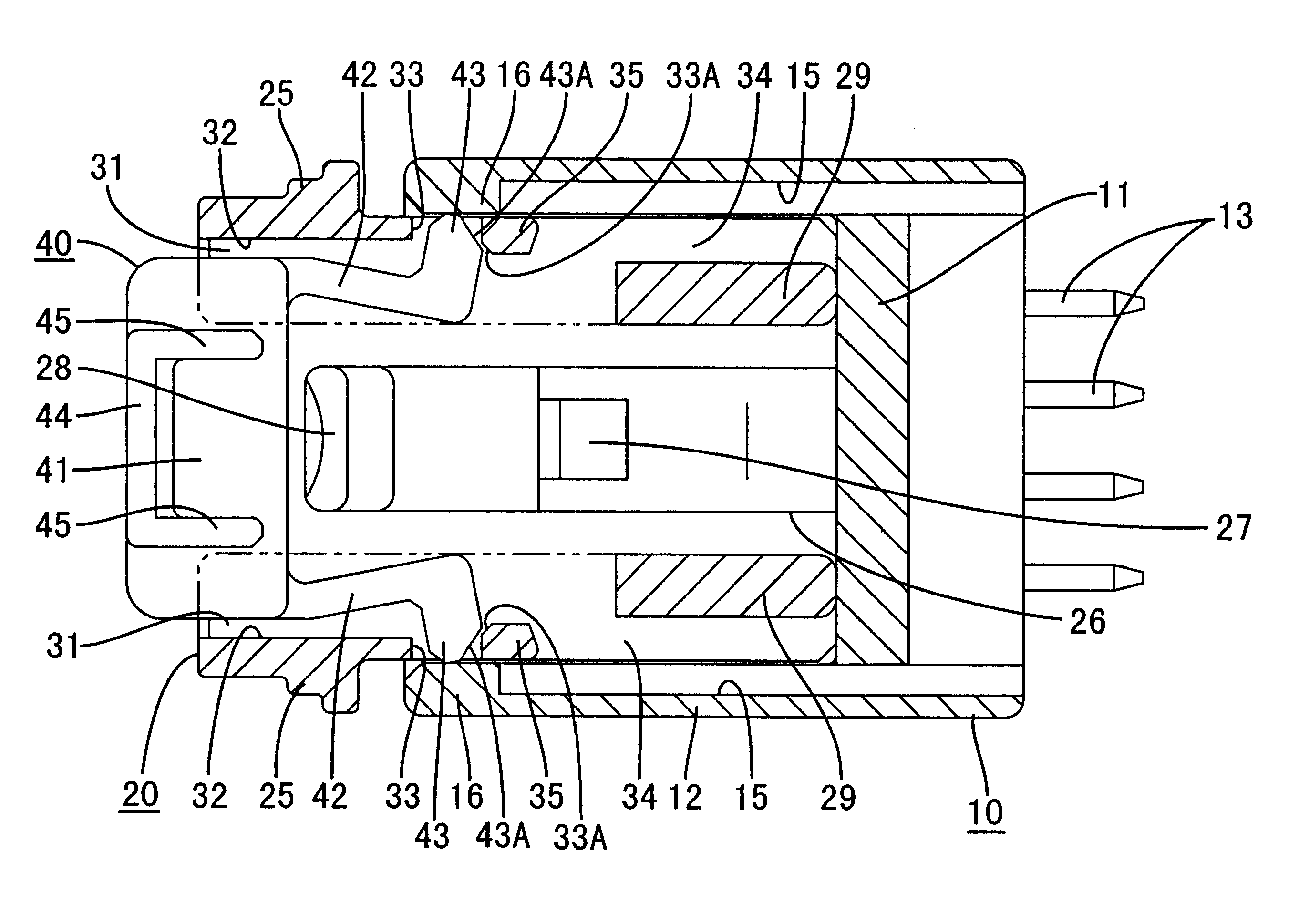
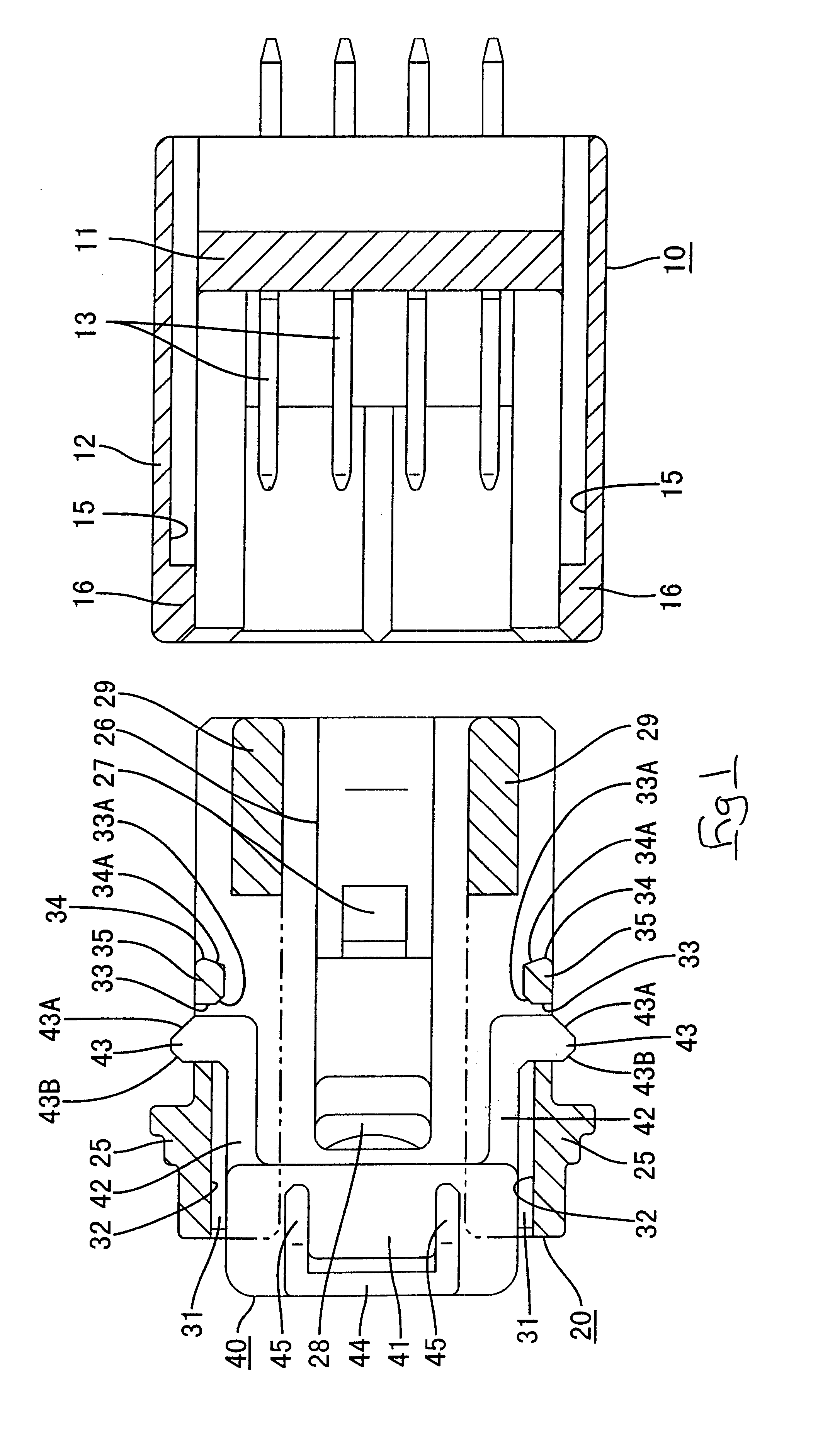
As shown in FIG. 1, a connector of the present embodiment is formed from a male connector housing 10 that fits with a female connector housing 20. A fitting detecting member 40, for ascertaining the fitting state of the connector, is attached to the female housing 20. Fitting face sides of the two housings 10 and 20 will hereafter be considered as the anterior sides.

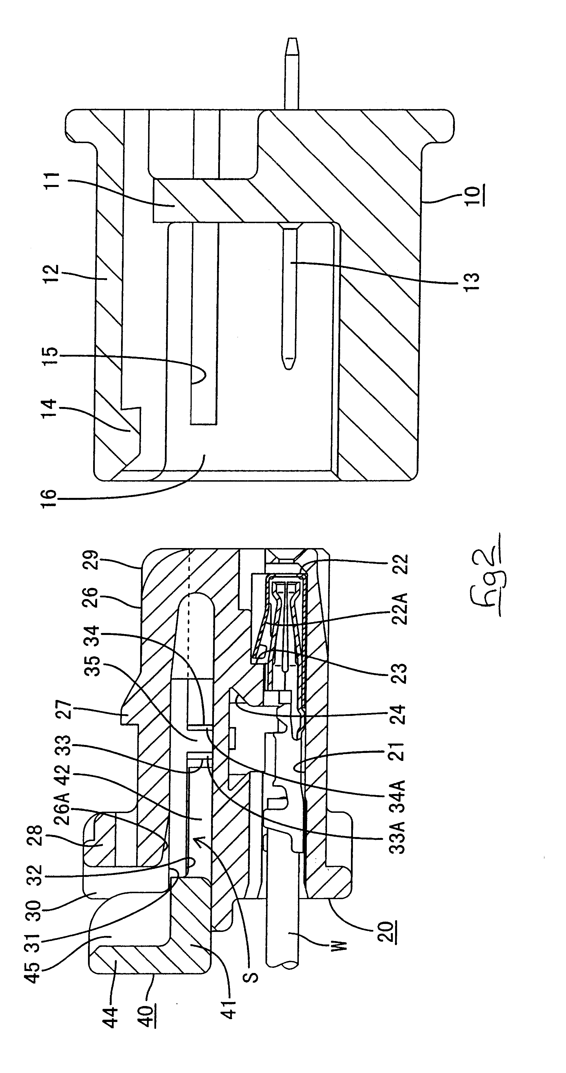
As shown in FIGS. 1 and 2, the male housing 10 is provided with a wall member 11 and a cylindrical hood 12, this hood 12 protruding towards the anterior from the wall member 11. The female housing 20 can be fitted within the hood 12. Four tab-shaped male terminal fittings 13, these being aligned in a width-wise direction, pass through the wall member 11. As shown in FIG. 2, a hook-shaped locking member 14 protrudes downwards from an upper portion of the hood 12. A resilient locking arm 26 of the female housing 20 engages with this locking member 14.

As shown in FIGS. 2 and 3, the female housing 20 has four cavities 21 ali...


PUM


Abstract

The invention avoids the problem of resilient stopping arms losing their resilience. A female housing has a locking arm capable of engaging with a locking member of a male housing protruding therefrom. A detecting member is attached to a posterior side of this female housing. A pair of resilient stopping legs extend in an anterior direction from a main body of the detecting member. Anterior end portions of the resilient stopping legs have outwardly protruding hook-shaped protrusions protruding therefrom, these engaging with temporary stopping holes or main stopping holes provided in side walls of the female housing. Retaining protrusions protrude further outwards from protruding anterior ends of the resilient stopping legs. These retaining protrusions protrude to the exterior of the female housing from the temporary stopping holes or the main stopping holes. Recessed grooves corresponding in location to the main stopping holes are formed in inner side faces of a hood of the male housing. The retaining protrusions that protrude from the main stopping holes are inserted into these recessed grooves in the hood. When the detecting member is in an operating position and the resilient stopping legs are in an inserted state within the main stopping holes, these resilient stopping legs return to their original free state.

Description

The present invention relates to an electrical connector, particularly a connector provided with a fitting detecting function.BACKGROUND TO THE INVENTIONOne example of a connector provided with a fitting detecting member for checking the fitting state of male and female connector housings is desribed in JP 11-26089. This connector has a locking arm provided on an upper face of a female housing that fits within a hood of a male connector, this locking arm engaging with a locking member provided in the male connector. A pair of protecting walls protrude from left and right sides of the locking arm, and a detecting member is attached to the posterior of the locking arm. The detecting member can be inserted from a waiting position at the exterior of the locking arm to an operating position within a bending space of the locking arm. While the locking arm is in a bent state while the two housings are being fitted together, the detecting member makes contact with the locking arm, thereby p...

Claims


Application Information

Patent Timeline
Patent Type & Authority Patents(United States)
IPC IPC(8): H01R13/64H01R13/641H01R13/639
CPCH01R13/641
Inventor HASEGAWA, TERUAKI
Owner SUMITOMO WIRING SYST LTD
Why Eureka
Try Eureka